Optical cable lock installation method

An installation method and optical cable technology are applied in the installation field of optical cable locks, which can solve the problems affecting the safe operation of optical communication networks, pulling out and breaking optical fiber cores, etc., so as to overcome the cumbersome installation and maintenance steps, reduce the failure rate, increase the The effect of friction

Active Publication Date: 2015-09-23
STATE GRID CORP OF CHINA +1
View PDF6 Cites 2 Cited by
  • Summary
  • Abstract
  • Description
  • Claims
  • Application Information

AI Technical Summary

Problems solved by technology

Generally, the terrain in mountainous areas is complex. When the cable tension changes due to mountain movement, temperature changes, and manual excavation vibrations, etc., failures such as the fiber core of the cable being pulled out or broken due to the failure of the connector box to hold the cable often occur, seriously affecting Safe Operation of Optical Communication Network

Method used


Image

  • Optical cable lock installation method
  • Optical cable lock installation method
  • Optical cable lock installation method

Examples


Embodiment Construction

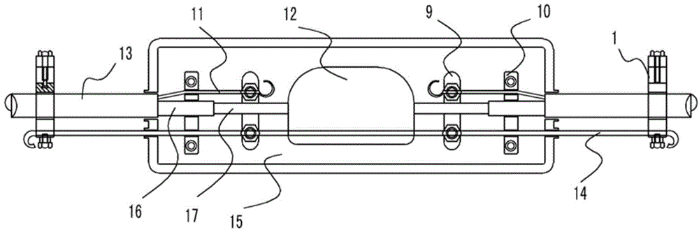
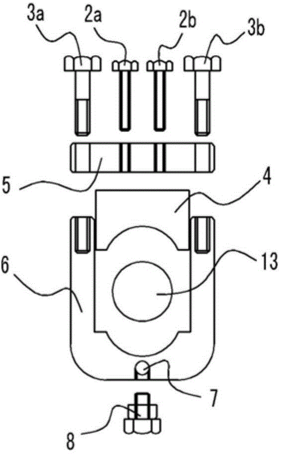
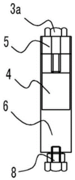
[0036] In this example, if figure 2 , image 3 Shown, the composition of a kind of optical cable lockset comprises:

[0037] A "U"-shaped lower clamp 6, the inner bottom of the "U"-shaped lower clamp 6 is provided with a semicircular groove, and the outer bottom of the "U"-shaped lower clamp 6 is provided with a blind hole 7 with a threaded structure; Fixing screw holes are respectively provided on the top end faces of both sides of the "U"-shaped lower holding clip 6;

[0038] One upper holding clip 4, the outer side of the upper holding clip 4 fits the inner side wall of the "U"-shaped lower holding clip 6, and the bottom of the upper holding clip 4 is provided with a semicircular groove corresponding to the "U"-shaped lower holding clip 6. Matching semicircular arch grooves; semicircular grooves and semicircular arch grooves form a fixed cavity for the optical cable 13;

[0039] A locking disc 5, the outer sides of the locking disc 5 are respectively provided with throu...


PUM


Abstract

The invention discloses an optical cable lockset and a mounting method of the optical cable lockset. The optical cable lockset is characterized by comprising a U-shaped lower holding clamp, an upper holding clamp, a locking plate, a fixing screw, a locking screw and a fastening screw; a semicircular groove is formed in the bottom of the inner side of the U-shaped lower holding clamp, and a semicircular arch groove matched with the semicircular groove of the U-shaped lower holding clamp is formed in the bottom of the upper holding clamp; a fixing cavity for an optical cable is formed by the semicircular groove and the semicircular arch groove; the fixing screw penetrates through a through hole of the locking plate to be fixed in the fixing screw hole on the end surface of the top of the U-shaped lower holding clamp; the locking screw penetrates through the locking screw hole in the locking plate to be fixed at the top of the upper holding clamp so as to form a locking structure for the optical cable; the fastening screw penetrates through a steel wire hole of the U-shaped lower holding clamp so as to form a fastening structure for a steel wire. According to the invention, not only can the optical cable be locked and fixed, but also most of tensile force born by a cable connector box is even decomposed when the tensile force of the optical force is enhanced, and a core of the optical cable is protected from damage.

Description

[0001] This application is a divisional application with the filing date: October 25, 2013, the application number: 2012101907356, and the name: an optical cable lock and its installation method. technical field [0002] The invention relates to an installation method of an optical cable lock applied to an optical fiber optical cable junction box. Background technique [0003] At present, the optical cables laid in the field of optical fiber cables are generally ordinary metal-free reinforced core optical cables. When these optical cables are laid across suburbs or hilly areas, the length is more than 200 kilometers. Generally, the terrain in mountainous areas is complex. When the cable tension changes due to mountain movement, temperature changes, and manual excavation vibrations, etc., failures such as the fiber core of the cable being pulled out or broken due to the failure of the connector box to hold the cable often occur, seriously affecting Secure operation of optical...

Claims


Application Information

Patent Timeline
Patent Type & Authority Applications(China)
IPC IPC(8): G02B6/44
CPCG02B6/4441
Inventor 程洪江龙才
Owner STATE GRID CORP OF CHINA
Why Eureka
Try Eureka