
Coordinate type positioning device of shell-and-tube heat exchanger cleaning facility

A technology for tube heat exchangers and cleaning equipment, which is applied in the direction of cleaning heat transfer devices, lighting and heating equipment, etc., can solve the problems of low efficiency, high labor intensity, unsatisfactory cleaning effect, etc., and achieve accurate positioning and low labor intensity. , ideal cleaning effect

Inactive Publication Date: 2015-09-23
TIANJIN TONGJIE HIGH PRESSURE PUMP
View PDF7 Cites 0 Cited by
  • Summary
  • Abstract
  • Description
  • Claims
  • Application Information

AI Technical Summary

Problems solved by technology

[0002] Shell and tube heat exchangers are widely used in the chemical industry and sugar industry. This kind of heat exchanger has multiple heat exchange tubes inserted on the end plate. Dirt will inevitably adhere to the tubes, which will affect the heat exchange effect and increase energy consumption. At present, the common methods to improve the heat exchange effect are manual cleaning, hand-held high-pressure water gun cleaning or mechanical cleaning, but manual cleaning is difficult for personnel and labor-intensive. Low efficiency and unsatisfactory cleaning effect; during mechanical cleaning, the center of gravity of the high-pressure water pipe holder is prone to shift and unstable movement, and the high-pressure water gun causes inaccurate positioning and deviation during the cleaning process of the down-travel pipe. The friction between the nozzle of the heat pipe and the pipe wall causes great wear and tear on the high-pressure water pipe. In addition, when the driving device of the high-pressure water gun slides, due to the offset of the center of gravity, it often appears to be stuck and shut down, which affects the normal cleaning work of the heat exchange pipe cleaning machine. Seriously affect the service life of the heat exchanger

Method used


Image

  • Coordinate type positioning device of shell-and-tube heat exchanger cleaning facility
  • Coordinate type positioning device of shell-and-tube heat exchanger cleaning facility

Examples


Embodiment Construction

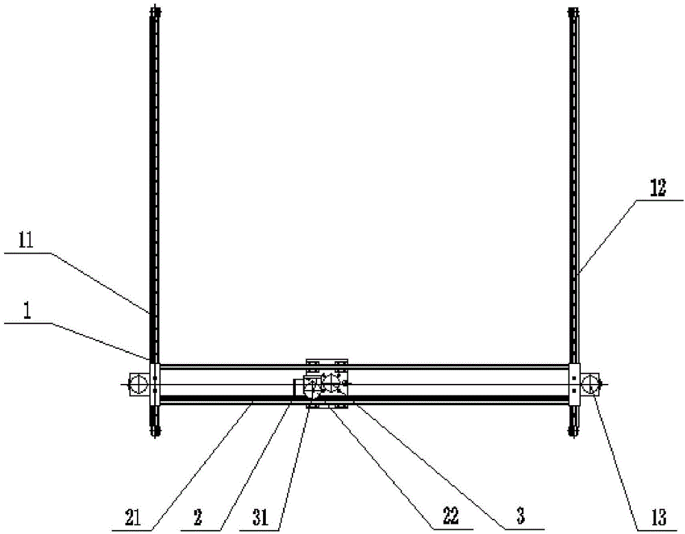
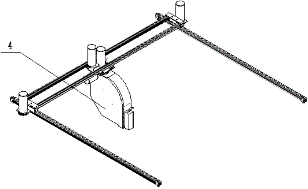
[0016] Such as Figure 1 to Figure 2 As shown, a coordinate positioning device in the tube heat exchanger cleaning equipment of the present invention includes a horizontal moving mechanism 2, a vertical moving mechanism 1 and a self-rotating mechanism 3, and the horizontal moving mechanism 2 includes a horizontal The guide rail 21 is provided with a horizontal movement drive mechanism 22 that is coupled to the horizontal guide rail 21 in the form of a rack and pinion; the horizontal movement drive mechanism 22 is fixedly connected to the self-rotation mechanism 3 through a sliding mounting base 31; Described vertical direction moving mechanism 1 comprises the first vertical guide rail 11 and the second vertical guide rail 12 that are symmetrically arranged on the two ends of horizontal guide rail 21; Mechanisms 2 are arranged perpendicular to each other; the two ends of the horizontal guide rail 21 are fixedly connected with a vertical movement drive mechanism 13; The racks a...


PUM


Abstract

Disclosed is a coordinate type positioning device of a shell-and-tube heat exchanger cleaning facility. The coordinate type positioning device comprises a horizontal movement mechanism, a vertical movement mechanism and a self-rotation mechanism. The horizontal movement mechanism comprises a horizontal guide rail, wherein a horizontal movement driving mechanism is arranged on the horizontal guide rail, and the horizontal movement driving mechanism and the horizontal guide rail are matched and connected with each other in a pinion and rack mode. The horizontal movement driving mechanism and the self-rotation mechanism are fixedly connected through a sliding installation base. The vertical movement mechanism comprises a first vertical guide rail and a second vertical guide rail, wherein the first vertical guide rail and the second vertical guide rail are symmetrically arranged at the two ends of the horizontal guide rail. The first vertical guide rail and the horizontal movement mechanism are arranged to be perpendicular to each other, and the second guide rail and the horizontal movement mechanism are arranged to be perpendicular to each other. Vertical movement driving mechanisms are fixedly connected to the two ends of the horizontal guide rail respectively. One vertical movement driving mechanism and the first vertical guide rail are matched and connected with each other through a pinion and a rack, and the other vertical movement driving mechanism and the second vertical guide rail are matched and connected with each other through a pinion and a rack. The coordinate type positioning device has the advantages of being accurate in positioning, low in labor intensity and ideal in cleaning effect.

Description

technical field [0001] The invention belongs to the technical field of cleaning equipment, and in particular relates to a coordinate positioning device in the cleaning equipment of tube-and-tube heat exchangers. Background technique [0002] Shell and tube heat exchangers are widely used in the chemical industry and sugar industry. This kind of heat exchanger has multiple heat exchange tubes inserted on the end plate. Dirt will inevitably adhere to the tubes, which will affect the heat exchange effect and increase energy consumption. At present, the common methods to improve the heat exchange effect are manual cleaning, hand-held high-pressure water gun cleaning or mechanical cleaning, but manual cleaning is difficult for personnel and labor-intensive. Low efficiency and unsatisfactory cleaning effect; during mechanical cleaning, the center of gravity of the high-pressure water pipe holder is prone to shift and unstable movement, and the high-pressure water gun causes inaccu...

Claims


Application Information

Patent Timeline
Patent Type & Authority Applications(China)
IPC IPC(8): F28G15/00F28G15/04
Inventor 齐永健
Owner TIANJIN TONGJIE HIGH PRESSURE PUMP
Learn More