
Pipe-in-pipe underground fluid stratified sampling device

A subsurface fluid and sampling device technology, applied in the direction of wellbore/well components, earthwork drilling, etc., can solve the problem of increasing the cross-sectional area of ​​the sampling system, drilling diameter, increasing control difficulty and system failure rate, sealing system and formation Problems such as difficulty in layer sealing, achieve clear and stable system control, good interlayer sealing effect, and improved stability and operability

Active Publication Date: 2015-09-23
INST OF ROCK AND SOIL MECHANICS - CHINESE ACAD OF SCI
View PDF11 Cites 17 Cited by
  • Summary
  • Abstract
  • Description
  • Claims
  • Application Information

AI Technical Summary

Problems solved by technology

However, there are still the following points worthy of improvement: 1) The application depth is limited, generally no more than -30m underground, which is mainly limited by the pressure resistance of plastic materials and quick connectors; 2) The number of layers of layered sampling is limited by simple isolation Generally, 2-3 layers are realized. If more layers are required to be sampled at the same time, the cross-sectional area of ​​the sampling system and the matching drilling diameter need to be increased; 3) There are many pipelines in the sampling system (such as application The downhole sampling device in a certain project contains 8 pipelines), which brings substantial difficulties to the isolation system and the sealing between formation layers, and increases the difficulty of control and the failure rate of the system

Method used


Image

  • Pipe-in-pipe underground fluid stratified sampling device
  • Pipe-in-pipe underground fluid stratified sampling device
  • Pipe-in-pipe underground fluid stratified sampling device

Examples


Embodiment Construction

[0029] The tool of the present invention will be described in detail below in conjunction with the accompanying drawings.

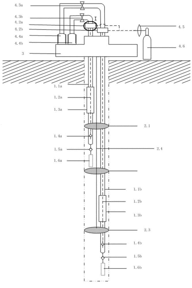
[0030] The structure of the pipe-in-pipe underground fluid layered sampling device provided by the present invention is as follows: figure 1 As shown, the device at least includes a pressure source 5, a wellhead fixing frame 3, a tube-in-tube downhole sampling mechanism 1, an isolation mechanism and a surface sampling mechanism. The well head holder 3 is used to fix the device when sampling.

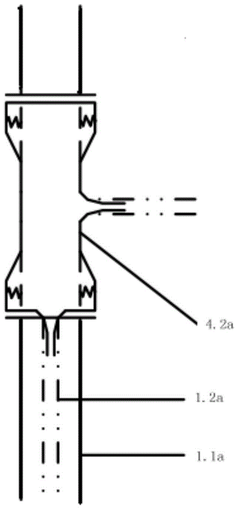
[0031] Tube-in-tube downhole sampling mechanism 1 includes a first tube-in-tube sampling mechanism and a second tube-in-tube sampling mechanism. The first tube-in-tube sampling mechanism includes a first outer tube 1.1a, a first inner tube 1.2a, The first flow storage container 1.3a, the first gas phase one-way valve 1.4a, the first liquid phase one-way valve 1.5a and the first filter element 1.6a. The first inner tube 1.2a is located inside the first outer tube 1...


PUM


Abstract

The invention provides a pipe-in-pipe underground fluid stratified sampling device. The pipe-in-pipe underground fluid stratified sampling device at least comprises a pressure source, a well head fixing frame, a pipe-in-pipe underground sample introducing mechanism, a packing mechanism and a ground sampling mechanism, wherein the well head fixing frame is used for fixing the device. The pressure source provides sampling power. The pipe-in-pipe underground sample introducing mechanism is a pipe-in-pipe system and performs pipeline arrangement for underground fluid sampling. The ground sampling mechanism transmits power of a power source to the pipe-in-pipe underground sample introducing mechanism and pumps underground fluid to the ground, and then the underground fluid is collected and sampled. The gas push type sampling principle is still adopted for the device, a U-shaped pipe system is upgraded into a pipe-in-pipe system, the number of stratified sampling layers is doubled, bearing force is doubled, sampling depth is extended from a -30 m level to a -200 m level, the structure of the device is greatly simplified, stability and operability are greatly improved, and therefore the competitive advantage of the device in the field of underground fluid sampling devices is further enhanced.

Description

technical field [0001] The invention relates to the technical field of underground fluid sampling, in particular to a pipe-in-pipe underground fluid layered sampling device, which is suitable for layered high-precision sampling of underground fluid. Background technique [0002] Subsurface fluid is an important factor related to the evolution of the earth and the survival of surface organisms. Subsurface fluid sampling can continuously provide a large amount of physical, chemical and microbial information about the formation through isotope tracking, formation residual gas analysis, chemical composition testing, microbial community characteristics and other analysis methods, which is of great guiding significance for engineering development and environmental safety assessment One of the means of monitoring. [0003] To analyze subsurface fluids, a subsurface fluid sample must first be obtained. According to the classification of working principles, various subsurface fluid...

Claims


Application Information

Patent Timeline
IPC IPC(8): E21B49/08
Inventor 刘学浩李小春肖威李琦宋然然方志明
Owner INST OF ROCK AND SOIL MECHANICS - CHINESE ACAD OF SCI
Learn More