
Punching device based on laser positioning and board adjustment and method thereof

A laser positioning and punching device technology, which is applied in the field of sheet metal processing, can solve the problems of low punching accuracy, easy deformation of the plate, lack of support devices, etc., and achieve the effect of preventing overall deformation and avoiding external collision damage

Inactive Publication Date: 2015-09-23
SUZHOU JINGYU AUTOMATION TECH
View PDF4 Cites 1 Cited by
  • Summary
  • Abstract
  • Description
  • Claims
  • Application Information

AI Technical Summary

Problems solved by technology

The above-mentioned punching devices or punching machines are generally operated manually, that is, the plate is adjusted by manually adjusting the clamping device to adjust the processing position. The disadvantages are: the positioning of the plate is not accurate, and the punching accuracy is not high; and lack of support devices, the plate Easy to deform, affecting processing quality

Method used


Image

  • Punching device based on laser positioning and board adjustment and method thereof

Examples


Embodiment Construction

[0015] The specific implementation manner of the present invention will be described below in conjunction with the accompanying drawings.

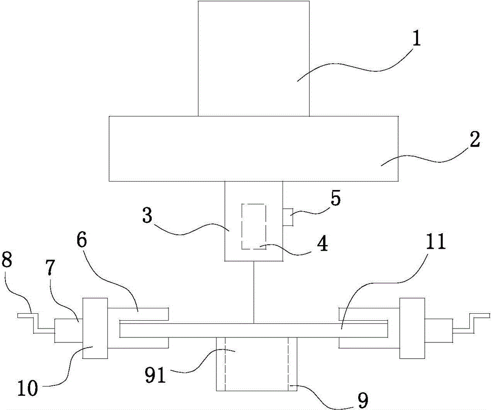
[0016] See figure 1 , the present invention includes a punching driving device 1, an upper template 2 and a punching head 3, and also includes a clamping device and a support block 9 positioned below the punching head 3, the clamping device includes a symmetrically arranged clamping block 6, clamping The holding block 6 is installed on the bracket 10 by means of the screw shaft 7, the outer end of the screw shaft 7 is connected with the handle 8, and the supporting block 9 has a punching groove 91; the laser head 4 is installed in the punching head 3 by means of the set screw 5.

[0017] The punching head 3 and the support block 9 of the present invention are all fixed on the frame (not shown). position, then start the laser head 4, the laser beam of the laser head 4 is irradiated on the workpiece 11, and a small mark is made, and the cla...


PUM


Abstract

The invention relates to a punching device based on laser positioning and board adjustment and a method thereof. The punching device comprises a punching drive device, an upper die plate and a punching head and further comprises a clamping device located below the punching head and supporting blocks. The clamping device comprises symmetrically arranged clamping blocks, and the clamping blocks are arranged on a bracket by the aid of a spiral shaft. The outer end of the spiral shaft is connected with a handle. The supporting blocks are provided with punched grooves. A laser head is arranged in the punching head by the aid of a set screw. According to the punching device, the machined position of the machined part is accurately adjusted through the laser head and the clamping blocks, the laser head is arranged in the punching head and does not occupy indoor space, and therefore the laser head can be prevented from being damaged by external collision; as the supporting blocks are arranged on the lower surface of the machined part, overall deformation of the machined part is prevented; the supporting blocks are provided with punched grooves, so punching materials can be conveniently discharged.

Description

technical field [0001] The invention relates to the technical field of sheet metal processing, in particular to a sheet metal punching machine. Background technique [0002] Existing punching devices or punching machines all include a frame, a bottom mold fixed on the frame, an upper template that moves up and down relative to the frame, and a punch corresponding to the bottom mold is fixed on the upper template. , the upper template is connected with the oil cylinder or cylinder that drives it to move up and down. Driven by the oil cylinder or air cylinder, the upper template drives the punch to move up and down relative to the bottom die, so as to punch out the required holes on the workpiece between the punch and the bottom die. The above-mentioned punching device or punching machine generally adopts a manual operation mode, that is, the plate is adjusted by manually adjusting the clamping device to adjust the processing position. The disadvantages are: the positioning o...

Claims


Application Information

Patent Timeline
Patent Type & Authority Applications(China)
IPC IPC(8): B21D28/34B21D28/26B21D43/00B21D45/06
CPCB21D28/34B21D28/26B21D43/003
Inventor 不公告发明人
Owner SUZHOU JINGYU AUTOMATION TECH
Learn More