A manual interlocking and locking device with three-station mechanism controlling point-to-point function

A locking device and control point technology, which is applied in the direction of electrical components, electric switches, circuits, etc., can solve the problems of inconvenient manual operation and failure to meet the user's operating conditions, and achieve complete functions, beautiful appearance, and improved reliability and quality. Effect

Active Publication Date: 2017-03-22
西安西电高压开关操动机构有限责任公司 +1
View PDF5 Cites 0 Cited by
  • Summary
  • Abstract
  • Description
  • Claims
  • Application Information

AI Technical Summary

Problems solved by technology

In order to completely eliminate the possibility of human misoperation, some users require that the operating power be provided only when a certain equipment is being repaired and operated, which requires separate power supplies for the DS side and ES side of the three-position mechanism. The manual interlock on the DS side of the three-position mechanism and the manual interlock on the ES side share the same power circuit, which cannot meet the operating conditions proposed by the user for separately providing power to the DS and ES.
At the same time, the existing three-station mechanism needs to open the side door of the mechanism during manual operation, causing inconvenience to the user for manual operation

Method used


Image

  • A manual interlocking and locking device with three-station mechanism controlling point-to-point function
  • A manual interlocking and locking device with three-station mechanism controlling point-to-point function
  • A manual interlocking and locking device with three-station mechanism controlling point-to-point function

Examples


Embodiment Construction

[0036] The present invention is described in further detail below in conjunction with accompanying drawing:

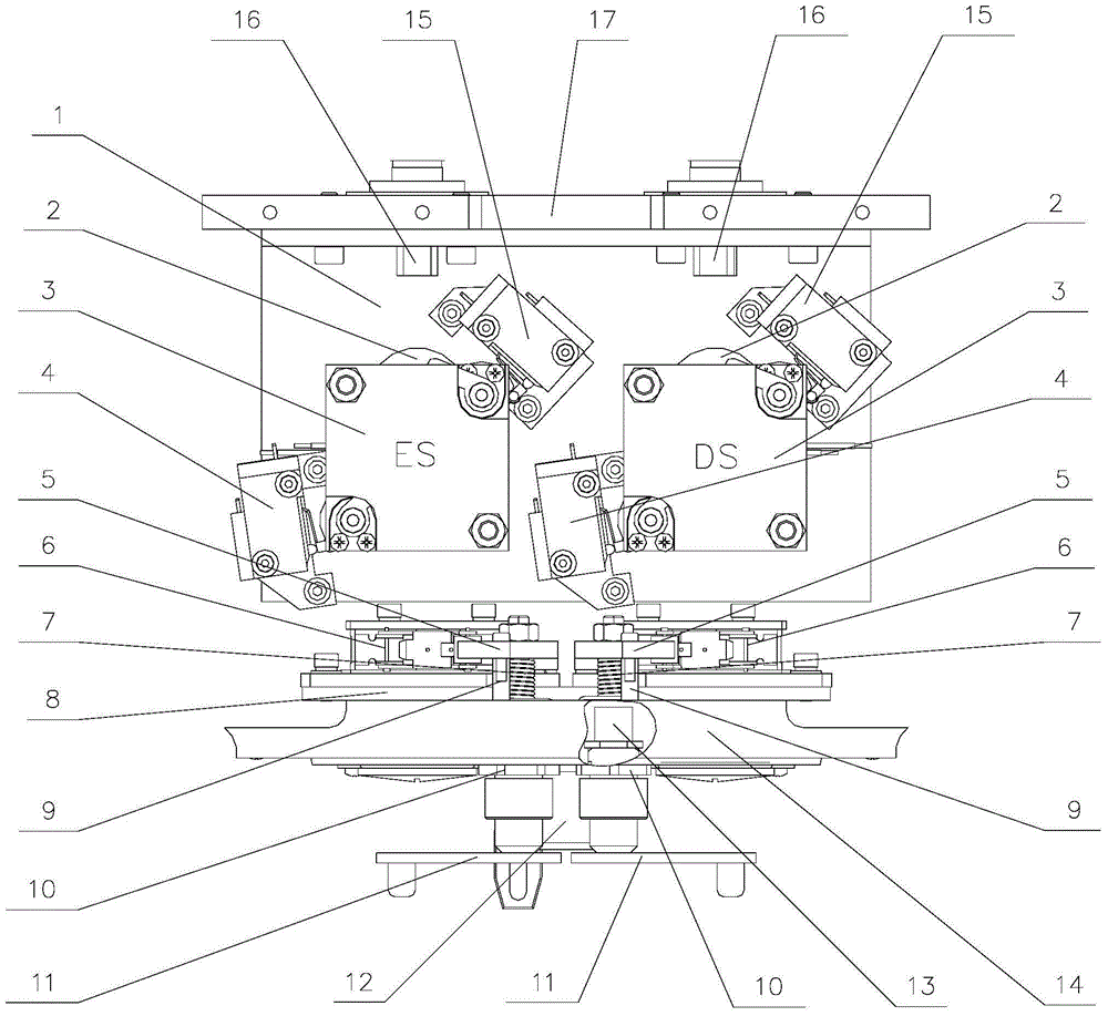
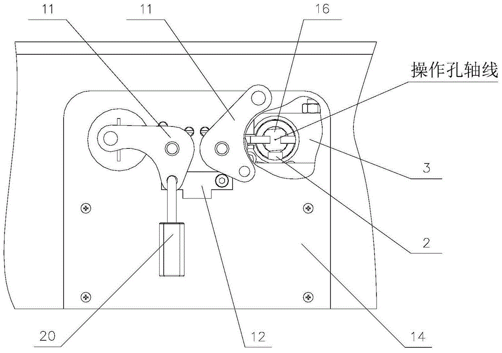
[0037] see Figure 1 to Figure 9 , the present invention includes a manual interlocking device installed on the movement side plate 17 and a manual locking device installed on the mechanism box 14;

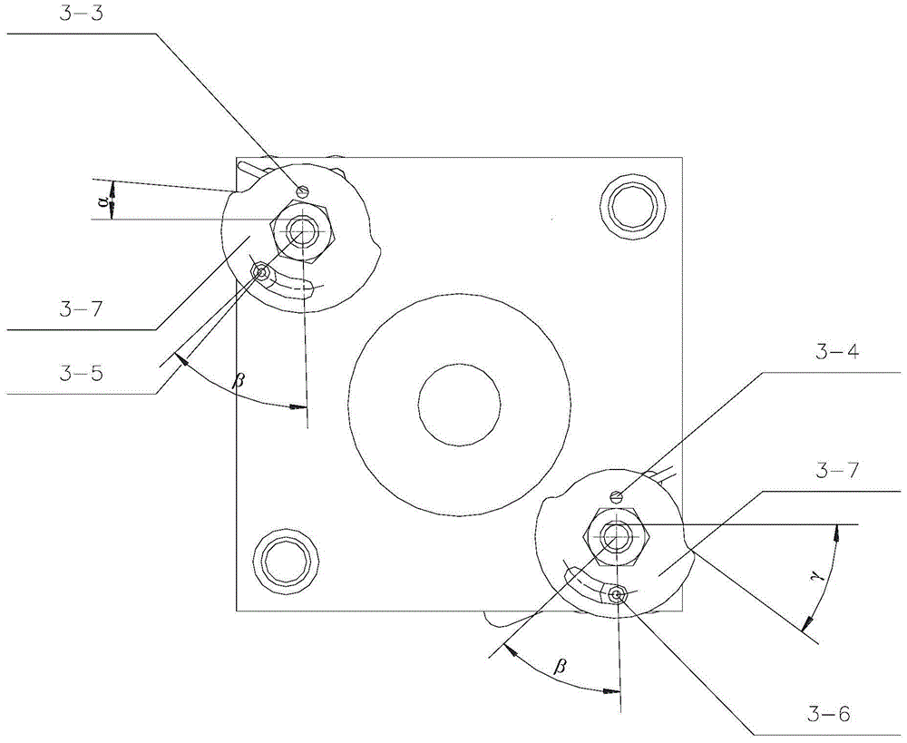
[0038] The manual interlocking device includes a support plate 1 installed on the movement side plate 17, and an interlock control module 3 installed on the DS side and the ES side of the support plate 1; the interlock control module 3 on the DS side and the ES side All are provided with an interlocking electromagnet 2 for electrically interlocking with other electrical components. The interlock control module 3 is provided with an operation hole matched with the operation handle, and the shaft of the operation hole is set coaxially with the lead screw 16 as the transmission part on the movement; An interlock power-on control switch assembly 4 and an interlock power-off ...


PUM


Abstract

The present invention discloses a manual interlocking and locking device with a three-station mechanism control point-to-point function, which comprises a manual interlocking device mounted on a machine core side plate and a manual locking device mounted on a mechanism case. According to the present invention, firstly, an operating handle pushes an interlocking power-on driving lever to rotate, cams on the same shaft simultaneously rotate, the cams press an electromagnet to enable the electromagnet to be powered on and a microswitch carries out state conversion, so that the interlocking electromagnet is powered on to be picked up; and the handle is continuously inserted, the operating handle pushes an interlocking power-off driving lever to rotate, the cams on the same shaft simultaneously rotate as well and press the electromagnet to enable the electromagnet to be powered off and the microswitch carries out state conversion, so that the interlocking electromagnet is powered off and the interlocking electromagnet is avoided being burnt down due to continuous electrification in the manual operating process. A power supply loop of the interlocking electromagnet is connected with an interlocking part outside a mechanism and if the external interlocking condition is not met, the interlocking electromagnet is always in a no-power state and the operating handle cannot be inserted into the mechanism so as to implement an interlocking function.

Description

[0001] 【Technical field】 [0002] The invention belongs to the technical field of high-voltage electrical equipment, and relates to a medium-voltage isolating switch and a high-voltage grounding switch of a gas-insulated metal fully-enclosed combined electrical appliance (GIS), in particular to a manual interlock and locking device with a three-station mechanism controlling point-to-point functions. [0003] 【Background technique】 [0004] In order to realize the miniaturization of high-voltage electrical appliances, the operation of high-voltage disconnector (DS) and high-voltage earthing switch (ES) has been improved from two separate operating mechanisms to one The three-position operating mechanism is operated to realize three different switching states: isolating switch open, grounding switch open; isolating switch closed, grounding switch open; isolating switch open, grounding switch closed. In order to avoid human misoperation and ensure the safety of personnel and power...

Claims


Application Information

Patent Timeline
Patent Type & Authority Patents(China)
IPC IPC(8): H01H9/26
CPCH01H9/26
Inventor 赵军亮
Owner 西安西电高压开关操动机构有限责任公司
Why Eureka
Try Eureka