A Quick Response Type Self-excited Magnetic Control Reactor

A magnetically controlled reactor, fast response technology, applied in the direction of transformer/inductor coil/winding/connection, transformer/inductor core, reactive power compensation, etc., can solve the problem of investment cost and increase of floor area, circuit structure and Complicated control strategies and increasing the difficulty of on-site process control, etc., to achieve the effect of improving utilization, realizing rapid response, and easy integrated design and production

Inactive Publication Date: 2016-08-17
LANZHOU JIAOTONG UNIV
View PDF5 Cites 0 Cited by
  • Summary
  • Abstract
  • Description
  • Claims
  • Application Information

AI Technical Summary

Problems solved by technology

[0003] However, with the increasing complexity of the grid load, the system has higher requirements for the response speed of dynamic reactive power compensation
Therefore, various quick improvement measures of self-excited magnetron reactors have also been studied in the prior art. Although there is a certain improvement effect, the corresponding circuit structure and control strategy become extremely complicated.
In particular, most of the measures adopt the method of increasing DC bias voltage or compound excitation, and it is necessary to provide a set of independent excitation sources, which not only greatly increases the investment cost and floor area, but also increases the difficulty of on-site process control.

Method used


Image

  • A Quick Response Type Self-excited Magnetic Control Reactor
  • A Quick Response Type Self-excited Magnetic Control Reactor
  • A Quick Response Type Self-excited Magnetic Control Reactor

Examples


Embodiment Construction

[0017] The principles and features of the present invention are described below in conjunction with the accompanying drawings, and the examples given are only used to explain the present invention, and are not intended to limit the scope of the present invention.

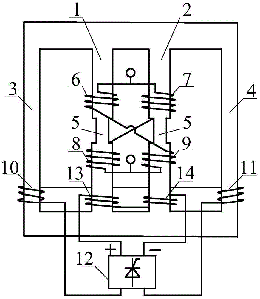
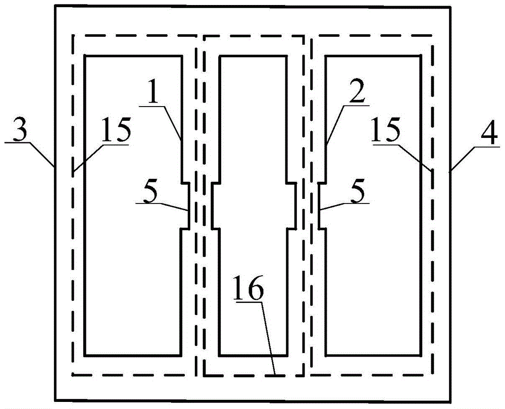
[0018] Such as Figures 1 to 3 As shown, the fast-response type self-excited magnetron reactor is characterized in that it includes a first iron core 1 and a second iron core 2, and the first iron core 1 is provided with a first working winding 6 and a fourth The working winding 9, the second working winding 7 and the third working winding 8 are arranged on the second iron core 2, the magnetic valve 5 is arranged between the first iron core 1 and the second iron core 2, and the first iron core 1 is correspondingly arranged on the side of the first iron core 1. On one side yoke 3, a first excitation winding 10 is arranged on the first side yoke 3, and a second side yoke 4 is arranged correspondingly on one side of th...


PUM


Abstract

The invention relates to the technical field of a dynamic reactive compensation device of electric energy quality control, and especially relates to a rapid response type self-excitation magnetically controlled reactor. The rapid response type self-excitation magnetically controlled reactor comprises a first iron core and a second iron core, wherein the first iron core is provided with a first working winding and a fourth working iron, the second iron core is provided with a second working winding and a third working winding, magnetic valves are arranged in the middle of the first iron core and the second iron core, one side of the first iron core is correspondingly provided with a first side yoke, the first side yoke is provided with a first excitation winding, one side of the second iron core is correspondingly provided with a second side yoke, the second side yoke is provided with a second excitation winding, the first iron core is also provided with a first control winding, the second iron core is also provided with a second control winding, and a controllable rectification apparatus is arranged between the first excitation winding and the second excitation winding and the first control winding and the second control winding. According to the invention, by use of a self-excitation type control loop and a cross series type working loop, the rapid response type self-excitation magnetically controlled reactor has the advantages of rapid response speed, simple structure and quite good comprehensive performance.

Description

technical field [0001] The invention relates to the technical field of dynamic reactive power compensation equipment for power quality control, in particular to a fast-response self-excited magnetic control reactor. Background technique [0002] The well-known magnetic valve type controllable reactor is referred to as a magnetic control reactor, which is a dynamic reactive power compensation device designed to work in a magnetic saturation state based on the principle of a magnetic amplifier. A magnetic valve with a slightly smaller area is set in its main core, and the DC bias is used to adjust the magnetic flux passing through the magnetic valve, thereby changing the saturation of the magnetic valve, thereby changing the output current of the reactor, and finally realizing the controllable capacity adjust. Because the controllable reactor with this working principle has obvious advantages such as simple maintenance, stable operation, high cost performance, and continuous ...

Claims


Application Information

Patent Timeline
Patent Type & Authority Patents(China)
IPC IPC(8): H01F27/24H01F27/30H02J3/18
CPCY02E40/30
Inventor 田铭兴石鹏太张俊强
Owner LANZHOU JIAOTONG UNIV
Why Eureka
Try Eureka