
Tower type solar optothermal and gas hybrid generation system

A tower-type solar energy and combined power generation technology, which is applied in the directions of solar thermal power generation, mechanical power generation by solar energy, steam generation, etc., can solve the problems of discontinuous energy utilization, expensive equipment and materials, and difficult realization, and achieve the goal of reducing startups. The effect of downtime and heat loss, low power consumption, and reduced input costs

Inactive Publication Date: 2015-09-16
HUADIAN DISTRIBUTED ENERGY ENG & TECH +1
View PDF7 Cites 1 Cited by
  • Summary
  • Abstract
  • Description
  • Claims
  • Application Information

AI Technical Summary

Problems solved by technology

[0004] Solar energy is the best renewable energy that is inexhaustible all over the world, but the use of solar energy resources also has its constraints, the biggest constraint is that solar energy can only be used in sunny days, Unavailable day and night, which leads to discontinuities in energy use
In order to realize the continuous power generation of solar energy, it needs to spend huge financial resources to build a huge energy storage system. Not only the equipment and materials used for energy storage are very expensive, but also there are various constraints that are not easy to realize, and the realization is relatively difficult.
For example, the solar tower power generation system needs to use some kind of gas, liquid or molten salt as the intermediate circulation medium, and ceramics, molten salt and other materials are used as the energy storage medium, which adds two more circulation systems and equipment virtually. Complicated, huge project, expensive materials, high power consumption

Method used


Image

  • Tower type solar optothermal and gas hybrid generation system

Examples


Embodiment 1

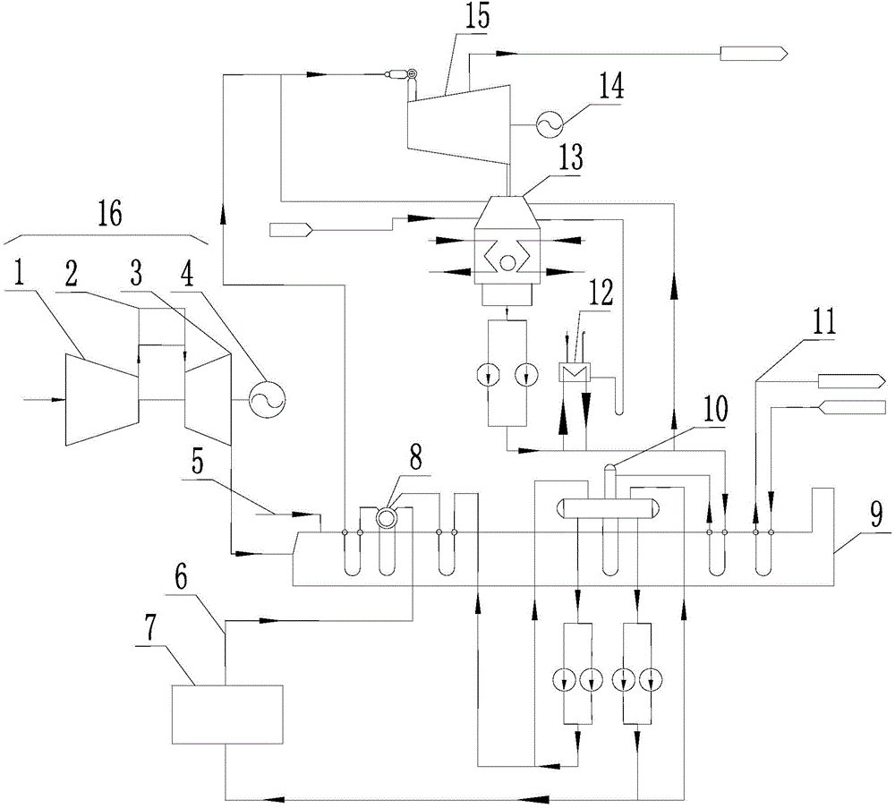
[0024] Embodiment 1 of the present invention: such as figure 1 As shown, a tower-type solar thermal and natural gas combined power generation system includes a gas-fired power generation system 16, a waste heat boiler 9, a tower-type solar thermal conversion system 7, a steam turbine 15 and a second generator 14. The steam turbine 15 is connected to the second generator 14, the gas-fired power generation system 16 is connected to the flue gas system of the waste heat boiler 9, the steam and water system of the steam turbine 15 is connected to the steam and water system of the waste heat boiler 9, and the tower solar thermal conversion system 7 is connected to the steam and water system. The circulation channel 6 communicates with the steam turbine 15. The gas power generation system 16 includes an air compressor 1, a combustion chamber 2, a gas turbine 3 and a first generator 4. The air compressor 1, the combustion chamber 2 and the gas turbine 3 are connected in sequence, the...


PUM


Abstract

The invention discloses a tower type solar optothermal and gas hybrid generation system, which comprises a gas turbine generation system, a waste heat boiler, a tower type solar optothermal conversion system and a gas turbine, wherein the gas turbine is connected with a second generator, a gas turbine exhaust system and a waste boiler gas and supplemental firing system are communicated, a main steam outlet of a waste heat boiler steam-water system is connected with a steam inlet system of the gas turbine, and supplemental water of the whole tower type solar optothermal and gas hybrid generation system directly enters a condenser. The tower type solar optothermal and gas hybrid generation system organically combines a gas generation system and a tower type solar optothermal generation system together to commonly generate, and further can supply steam according to demands simultaneously. The tower type solar optothermal and gas hybrid generation system can adjust electrical loads to meet the demands of power supply, alleviates the pressure of the power supply, reduces consumption of gas, also solves the problem that tower type solar optothermal generation systems are not easy to store energy at night, reduces cost input, and further can continuously run throughout the year simultaneously, thereby improving whole economic performance of projects.

Description

Technical field [0001] The invention relates to a power generation system, in particular to a tower-type solar thermal and natural gas combined power generation system. Background technique [0002] Natural gas power generation is one of the most stable distributed energy supply methods. An excellent combined cooling, heating and power generation system can increase the efficiency of gas power generation to more than 95%. From the development experience of developed countries in the world and some Southeast Asian countries, the development of distributed gas power generation systems is the only way to achieve energy conservation, emission reduction and sustainable development of energy supply. It has high efficiency, energy saving, emission reduction, environmental protection, and improvement of energy supply security. Combining many advantages such as cutting peaks and filling valleys in gas supply and promoting the development of circular economy, it is an irreversible trend in...

Claims


Application Information

Patent Timeline
Patent Type & Authority Applications(China)
IPC IPC(8): F01K11/02F01K23/10F03G6/00F02C6/18F22B33/18
CPCY02E10/46
Inventor 于秀艳徐海洲赵志渊
Owner HUADIAN DISTRIBUTED ENERGY ENG & TECH
Learn More