
Fabricated precast concrete box culvert

A prefabricated concrete and prefabricated technology, applied in shaft equipment, earthwork drilling, artificial islands, etc., can solve the problems of large investment in production equipment and hoisting equipment, long construction period of cast-in-place box culverts, and difficulty in producing equipment for box culverts. Achieve the effects of simple production and installation process, wide application range, convenient transportation and installation

Active Publication Date: 2015-09-16
南京钜砼建筑工业技术研究所有限公司
View PDF5 Cites 12 Cited by
  • Summary
  • Abstract
  • Description
  • Claims
  • Application Information

AI Technical Summary

Problems solved by technology

These two methods have great disadvantages: cast-in-place box culverts have a long construction period, high labor intensity, low efficiency, are greatly affected by weather and site conditions, cause huge pollution to the surrounding environment, unstable construction quality, and high cost ; The overall box culvert produced in a factory is limited to transportation and hoisting difficulties, especially for large box culverts, which require huge investment in production equipment and hoisting equipment, and super-sized box culverts are difficult to manufacture without production equipment

Method used


Image

  • Fabricated precast concrete box culvert
  • Fabricated precast concrete box culvert
  • Fabricated precast concrete box culvert

Examples


Embodiment Construction

[0020] In order to clearly illustrate the technical features of this solution, the present invention will be described in detail below through specific implementation modes and in conjunction with the accompanying drawings.

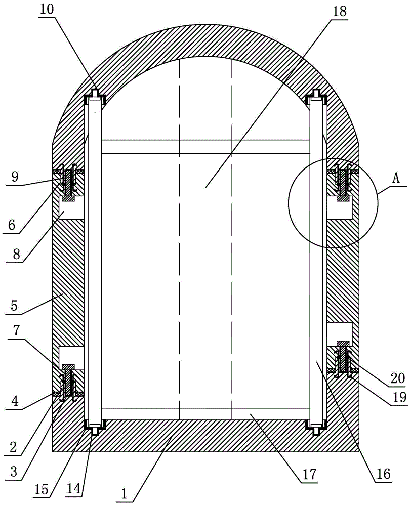
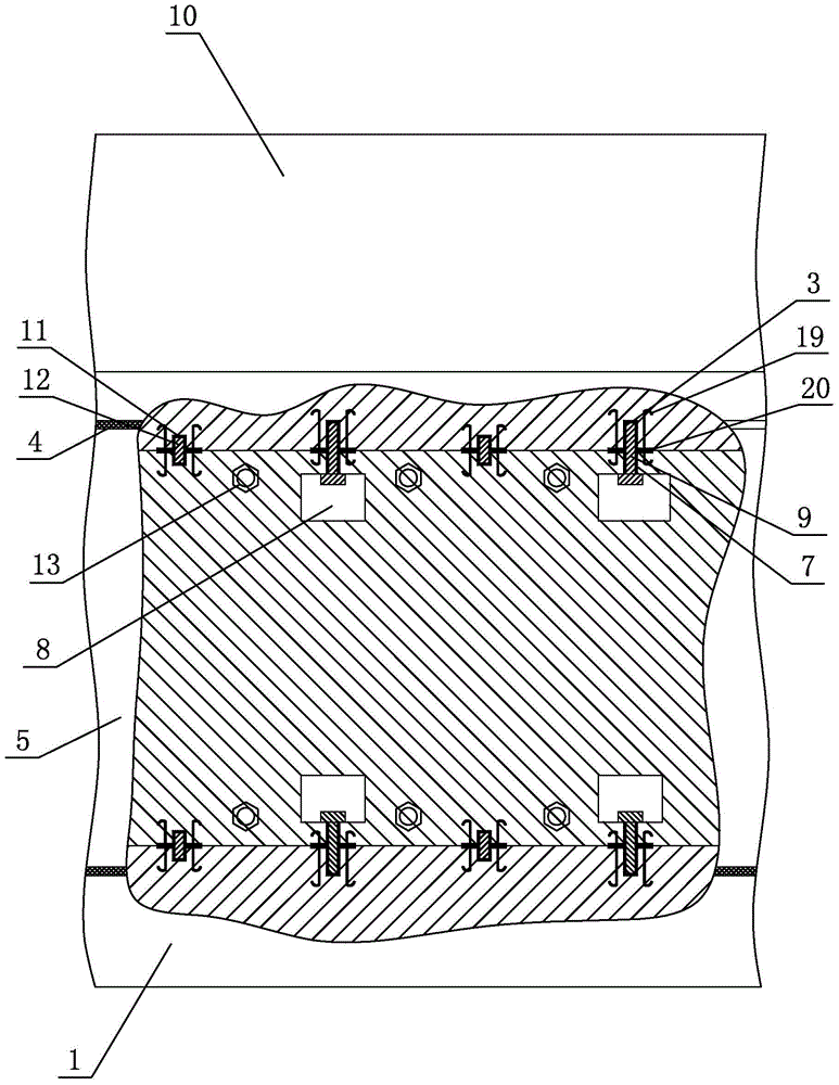
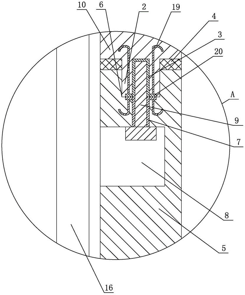
[0021] Such as Figure 1-3 As shown, an assembled prefabricated concrete box culvert includes a trough-shaped base 1 laid horizontally on the ground, and a boss is respectively arranged in the middle of the upper end surface of the vertical plate on both sides of the trough-shaped base 1 along the length direction of the trough-shaped base 1 2. On the top surface of the boss 2 along the length direction of the boss 2, several vertically arranged long hexagonal nuts 3 are embedded at intervals, and a rubber sealing ring 4 is set on the outer bottom of the boss 2. A wallboard 5 is vertically provided above the side vertical board respectively, and a groove 6 is respectively arranged along the length direction of the wallboard 5 in the middle part of the upp...


PUM


Abstract

The invention relates to a fabricated precast concrete box culvert. The fabricated precast concrete box culvert comprises a groove-type base paved on the ground horizontally. Bosses are arranged at the middle portions of the upper end faces of stand plates arranged at the two sides of the groove-type base in the length direction of the groove-type base respectively. Multiple long hexagon nuts which are arranged vertically are embedded on the end faces of the bosses in the length direction of the bosses at intervals. Rubber sealing rings are arranged at the outer sides of the bottoms of the bosses in a sleeving mode. Wallboards are vertically arranged above the stand plates arranged at the two sides of the groove-type base. Grooves are formed in the middle portions of the upper surfaces and the lower surfaces of the wallboards in the length direction of the wallboards respectively. Multiple steel jackets which are arranged vertically are arranged at the position, corresponding to the position of each long hexagon nut, of the middle portions of the bottom faces of the grooves in the length direction of the grooves. According to the fabricated precast concrete box culvert, the structure and design are reasonable, the transportation and installation are convenient, four precast concrete plate-shaped components are adopted for assembling, the transportation and installation for the plate-shaped components are convenient, industrialized production is adopted, the concrete strength is high, the quality can be controlled, the composite cost is low, the construction period is short, the quality is good, the application range is wide, and the advantages of being economical and environmental-friendly are possessed.

Description

Technical field: [0001] The invention relates to an assembled prefabricated concrete box culvert. Background technique: [0002] The installation and construction of traditional concrete box culverts generally either adopts the method of on-site pouring, or adopts centrifugal or vibration pouring in the factory to form a whole and transport it to the construction site. These two methods have great disadvantages: cast-in-place box culverts have a long construction period, high labor intensity, low efficiency, are greatly affected by weather and site conditions, cause huge pollution to the surrounding environment, unstable construction quality, and high cost The whole box culvert of factory production is limited to transportation and hoisting difficulties, especially for large box culverts, which requires huge investment in production equipment and hoisting equipment, and the oversized box culverts are difficult to have production equipment and cannot be manufactured. Invent...

Claims


Application Information

Patent Timeline
IPC IPC(8): E02D29/045E21D11/08
Inventor 李全民
Owner 南京钜砼建筑工业技术研究所有限公司
Learn More