
Construction method of a carrier pile

A construction method and technology of carrier piles, applied in sheet pile walls, foundation structure engineering, construction, etc., can solve problems such as reduced work efficiency, large restrictions, pile length, etc., to improve construction work efficiency, expand application types, and increase construction speed Effect

Active Publication Date: 2017-05-03
北京波森特岩土工程有限公司
View PDF1 Cites 0 Cited by
  • Summary
  • Abstract
  • Description
  • Claims
  • Application Information

AI Technical Summary

Problems solved by technology

However, with the development of urban construction, there are more and more high-rise buildings, and the requirements for the bearing capacity of piles are getting higher and higher, and the length of piles is also increasing again and again. restrict
Especially due to the continuous increase of the length of the pile body, the hardness of the soil layer at the pile end is also gradually increased, such as pebble layer, round gravel layer, moderately weathered and strongly weathered rock soil layer, sand layer and other soil layers. At this time, the above-mentioned patent is adopted. When the method is used to tamp the filler, there will be problems such as difficult construction and reduced work efficiency.
At the same time, due to the singleness of the construction means and mechanical devices of the above-mentioned patented method, the hole forming and pile forming methods in the pile body are relatively limited, which can no longer meet the changing needs of geological conditions and design requirements.

Method used


Image

  • Construction method of a carrier pile
  • Construction method of a carrier pile

Examples


Embodiment Construction

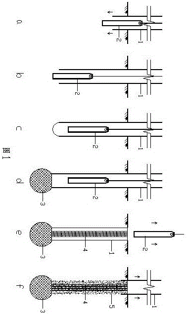
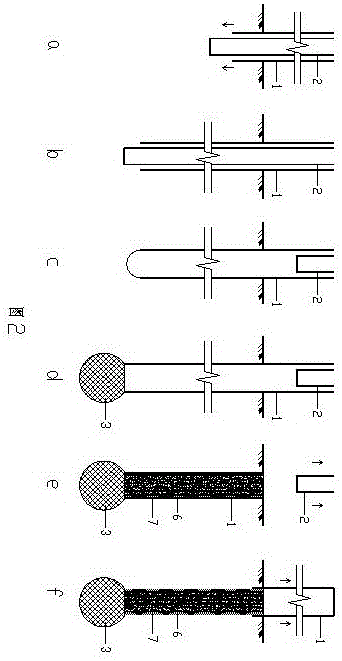
[0030] figure 1 It is a schematic diagram of an embodiment of the construction method of the carrier pile of the present invention, at first, as figure 1 As shown in a, at the pile position, through the free fall movement of the heavy hammer 2 in the casing 1, the foundation soil is punched to form pile holes and sink into the casing 1; then, as figure 1 As shown in middle b, sink the casing 1 and the weight 2 to the set depth, and drive the casing 1 out of the bottom of the weight 2 for a certain distance; then, as figure 1 As shown in middle c, in the casing 1, the soil mass at the bottom of the pile hole is tamped with the hammering kinetic energy of the weight 2, so that the soil mass at the pile tip is reinforced and compacted; then, as figure 1 As shown in d, repeat the above-mentioned tamping operation, and measure the penetration of the three-stroke penetration of the weight 1. When the measured value of the three-stroke penetration meets the design value, stop the ta...


PUM


Abstract

The invention aims to provide a carrier pile construction method. According to the characteristic that the soil layer where the pile end is located is harder, punning and compaction are conducted on the soil body of the pile end directly through kinetic energy, and the requirements of multiple geological conditions and design requirement change are met through the improvement of the pore-forming mode and the pile-forming mode. To achieve the purpose, the construction method includes the steps that 1, a pile casing or an outer tube is sunk into the set depth through power at the pile position; 2, punning is conducted on the soil body at the bottom of a pile hole through the hammering kinetic energy of a heavy hammer or an inner tube in the pile casing or the outer tube, and the soil body of the pile end is reinforced and compacted; 3, punning is conducted repeatedly, the penetration of several times of striking of the heavy hammer or the inner tube is measured, when the penetration measuring value meets the design value, punning is stopped, the soil body, within certain depth and range, below the pile end is reinforced and compacted, a pile end carrier is formed, and the equal calculation area Ae of the carrier pile is achieved; 4, pile body construction is conducted.

Description

technical field [0001] The invention relates to the field of civil engineering, in particular to the construction of piles. Background technique [0002] A new pile foundation technology is disclosed in Patent No. ZL98101041.5. The pile type includes a composite carrier and a concrete pile body. The filling material is tamped, and a composite carrier is formed at the pile end through the three-strike penetration control standard, so that the upper load can effectively pass through the pile and the composite carrier below the pile, and be transferred to the better bearing layer, thereby improving the bearing capacity of the pile It has the advantages of high single pile bearing capacity and economical cost. Therefore, the composite carrier of the above-mentioned patent method is usually arranged in a weak soil layer with a shallow buried depth. However, with the development of urban construction, there are more and more high-rise buildings, and the requirements for the beari...

Claims


Application Information

Patent Timeline
Patent Type & Authority Patents(China)
IPC IPC(8): E02D5/38
Inventor 王继忠
Owner 北京波森特岩土工程有限公司
Learn More