Liquid jet head and liquid jet apparatus
一种液体喷射头、液体的技术,应用在着墨装置、印刷等方向,能够解决记录品质下降等问题,达到有效冷却、简化连接的效果
- Summary
- Abstract
- Description
- Claims
- Application Information
AI Technical Summary
Problems solved by technology
Method used
Image
Examples
no. 1 approach
[0039] figure 1 It is a schematic diagram of the liquid jet head 1 according to the first embodiment of the present invention. This first embodiment shows the basic configuration of the present invention. like figure 1 As shown in , the liquid jet head 1 includes: a head 2 that discharges liquid droplets from a nozzle 6 ; a circuit unit 7 that supplies a drive waveform to the head 2 ; The head 2 includes: a supply flow path 3 that flows in a part of liquid supplied from the outside, circulates inside, and flows out to the outside; a pressure chamber 4 that communicates with the supply flow path 3 ; and a drive element 5 that drives the pressure chamber 4 ; and the nozzle 6 , which communicates to the pressure chamber 4 . The circuit unit 7 generates a driving waveform for driving the driving element 5 of the head 2 . The cooling unit 10 includes a cooling flow path 11 through which another part or the rest of the liquid supplied from the outside flows in, circulates inside...
no. 2 approach
[0044] figure 2 is a schematic perspective view of a liquid jet head 1 according to a second embodiment of the present invention, image 3 It is an explanatory diagram of the liquid jet head 1 according to the second embodiment of the present invention. image 3 (a) is a schematic front view of the liquid jet head 1 viewed from the front of the cooling unit 10, image 3 (b) is a schematic side view of the liquid jet head 1 viewed from the side of the cooling unit 10 and the circuit unit 7, image 3 (c) is a schematic cross-sectional view of the head 2 in a direction perpendicular to the reference direction K. FIG. The same symbols are assigned to the same parts or parts with the same function.
[0045] like figure 2 and image 3 As shown in , the liquid ejection head 1 is provided with: a head 2, which ejects liquid droplets downward; a base member 18, to which the head 2 is fixed; a supply port 13 and a discharge port 14, which are provided on the base member 18. The ...
no. 3 approach
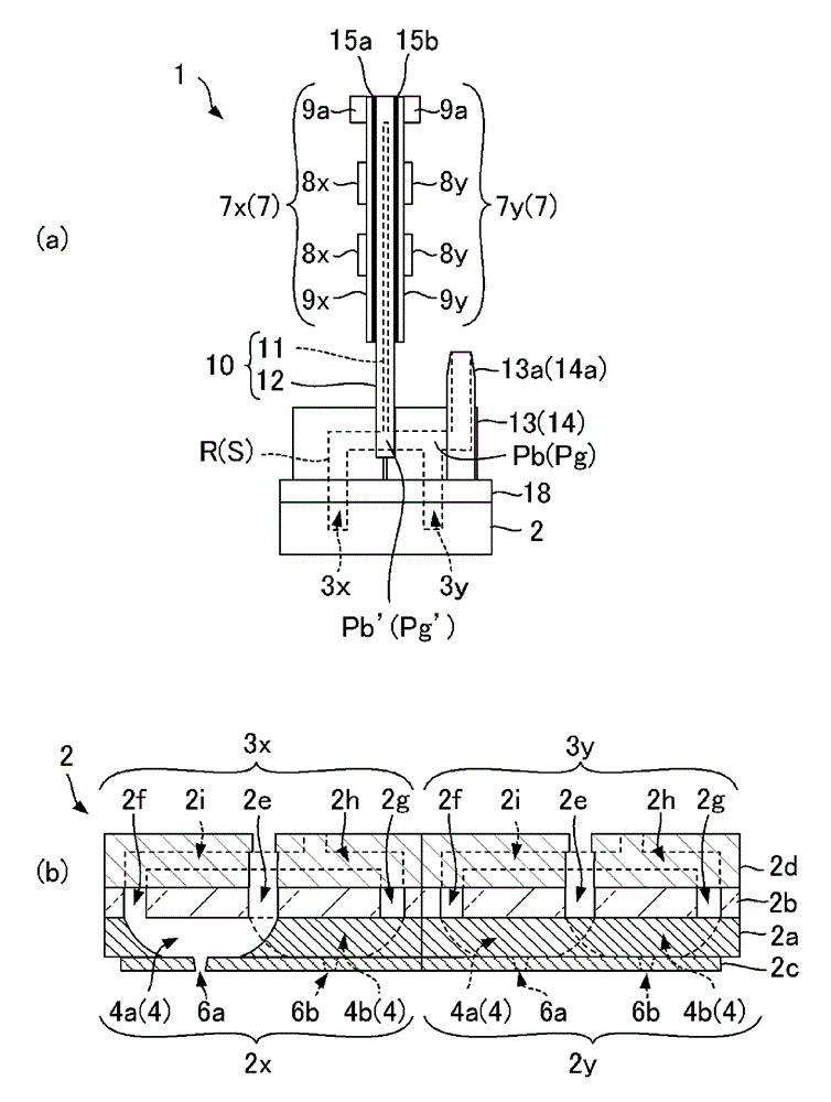
[0053] Figure 4 It is an explanatory diagram of the liquid jet head 1 according to the third embodiment of the present invention. Figure 4 (a) is a schematic side view of the liquid jet head 1, Figure 4 (b) is a schematic cross-sectional view of the head 2 in a direction perpendicular to the reference direction K. FIG. The main difference from the second embodiment is that the first and second circuit parts 7x, 7y are connected and fixed to the cooling part 10, and the head part 2 is provided with the first and second supply channels 3x, 3y. The same symbols are assigned to the same parts or parts with the same function.
[0054] like Figure 4 As shown in , the liquid ejection head 1 is provided with: a head 2, which ejects liquid droplets downward; a base member 18, to which the head 2 is fixed; a supply port 13 and a discharge port 14, which are provided on the base member 18. The side opposite to the head 2; the cooling part 10, which is fixed to the supply port 13 ...
PUM
 Abstract
Description
Claims
Application Information
 - R&D Engineer
- R&D Manager
- IP Professional
- Industry Leading Data Capabilities
- Powerful AI technology
- Patent DNA Extraction
Browse by: Latest US Patents, China's latest patents, Technical Efficacy Thesaurus, Application Domain, Technology Topic, Popular Technical Reports.
© 2024 PatSnap. All rights reserved.Legal|Privacy policy|Modern Slavery Act Transparency Statement|Sitemap|About US| Contact US: help@patsnap.com


