Sludge drying incineration system and method

A sludge drying and sludge technology, applied in chemical instruments and methods, combustion methods, separation methods, etc., can solve the problems of poor economic feasibility and high cost of sludge incineration

Active Publication Date: 2015-09-09
常州振业机械设备有限公司
View PDF10 Cites 12 Cited by
  • Summary
  • Abstract
  • Description
  • Claims
  • Application Information

AI Technical Summary

Problems solved by technology

This method requires a large amount of coal when incinerating sludge, and the weight ratio of dehydrated sludge to coal is 20-30:70-80, that is, burning one ton of sludge requires about 3.5-4 tons of coal, and the cost of sludge incineration is very high. High, poor economic viability

Method used


Image

  • Sludge drying incineration system and method
  • Sludge drying incineration system and method
  • Sludge drying incineration system and method

Examples


Embodiment 1

[0063] (Example 1, sludge drying and incineration system)

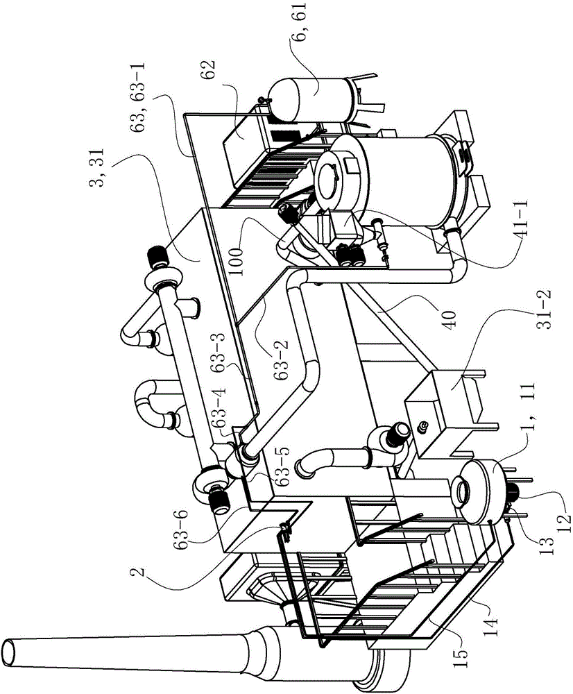
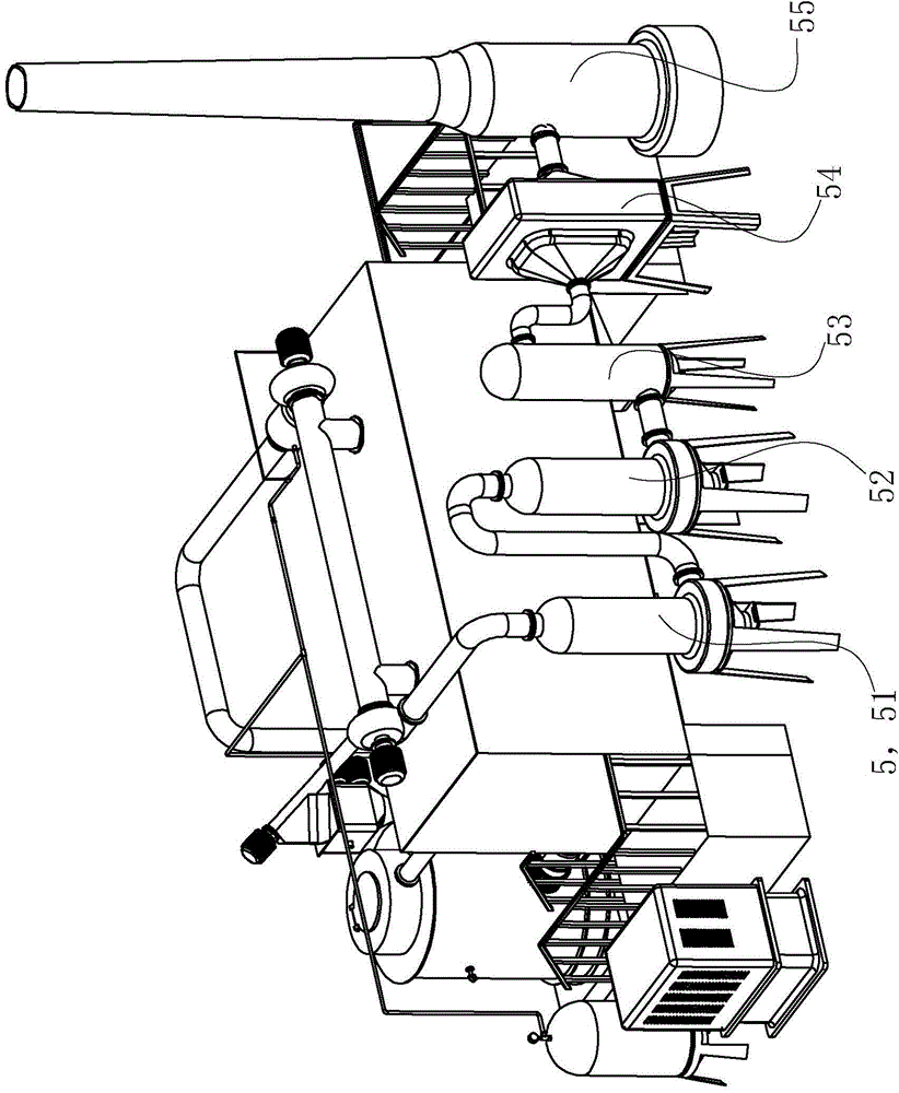
[0064] See figure 1 , The sludge drying and incineration system in this embodiment includes a wet sludge storage tank 1 , a sludge high-pressure injection device 2 , a drying device 3 , an incineration device 4 , a flue gas purification device 5 and an air supply device 6 .

[0065]The wet sludge storage tank 1 includes a tank body 11 , a stirring motor 12 , stirring paddles, a sludge pump 13 , a sludge feeding pipeline 14 and a sludge return pipeline 15 . Stirring motor 12 is arranged on the bottom outside of tank body 11, and the motor shaft of stirring motor 12 stretches into the inner chamber of tank body 11 from bottom to top, and motor shaft is connected with the stirring paddle inside tank body 11, drives stirring paddle to rotate. Sludge pump 13 is arranged on the bottom outside of tank body 11, and the mud inlet of sludge pump 13 is connected with the mud outlet of tank body 11 bottoms, and the mud outlet of...

Embodiment 2

[0096] (Example 2, sludge drying and incineration method)

[0097] The sludge drying and incineration method of this embodiment uses the sludge drying and incineration system described in Example 1, comprising the following steps:

[0098] ① Transport the sludge with a water content of 75% to 85% produced by the urban sewage treatment plant into the tank body 11 of the wet sludge storage tank 1, turn on the stirring motor 12 to stir the wet sludge evenly, and then turn on the sludge pump 13 The wet sludge is sent from the tank body 11 into the sludge high-pressure injection device 2 .

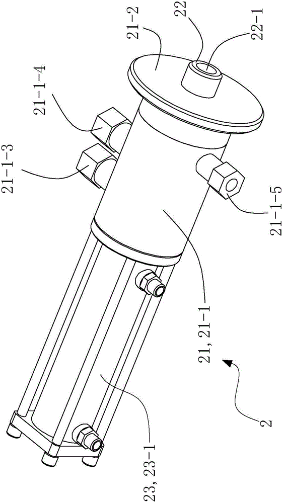
[0099]The wet sludge enters the sludge chamber 21-1a from the mud inlet 21-1-3 of the cylinder body 21-1 of the nozzle seat assembly 21, and then enters the sludge passage 22-1 of the nozzle 22, and the air compressor is turned on to pump the sludge to the cylinder. The air inlet 21-1-5 of the body 21-1 is fed with high-pressure hot air, and the negative pressure generated at this time will ta...


PUM


Abstract

The invention discloses a sludge drying incineration system and method. The sludge drying incineration system comprises a wet sludge storage tank, a sludge high-pressure injection device, a drying box, an incinerator, a fume cleaning device and a gas feeder, wherein a sludge outlet end of a sludge feed pipeline of the wet sludge storage tank is communicated with a sludge inlet of the sludge high-pressure injection device; a sludge spraying port of a sprayer of the sludge high-pressure injection device is communicated with a sludge inlet of the drying box; a first fume outlet of the drying device is communicated with a gas inlet of the incinerator; a second fume outlet of the drying device is communicated with the fume cleaning device; and a fume outlet of the incinerator is communicated with the drying device. The sludge drying incineration system utilizes heat carried by high-temperature fume generated by sludge incineration to dry the wet sludge, and completely utilizes the heat generated by sludge incineration in the drying stage without any other energy.

Description

technical field [0001] The invention relates to sludge treatment technology, in particular to a sludge drying and incineration system and method. Background technique [0002] In recent years, under the influence of national energy conservation and emission reduction and active fiscal policies, urban sewage treatment has developed rapidly, and urban water environment governance has achieved remarkable results. However, a large amount of sludge generated in the process of urban sewage treatment has not been generally effectively treated and disposed of. These sludges contain toxic and harmful substances such as pathogens, heavy metals, and persistent organic compounds. If they are not treated effectively, they will easily cause secondary pollution to groundwater, soil, etc., directly threatening environmental safety and public health, and greatly improving the environmental benefits of sewage treatment facilities. At the same time, it affects the positive effect of the imple...

Claims


Application Information

Patent Timeline
IPC IPC(8): C02F11/12C02F11/18F23G7/00B01D50/00B01D53/26B01D53/32
Inventor 贺国清唐政
Owner 常州振业机械设备有限公司
Why Eureka
Try Eureka