A countercurrent sludge drying device

A sludge drying and countercurrent technology, applied in the direction of dehydration/drying/thickened sludge treatment, etc., can solve the problems of limited sludge water reduction, failure to meet combustion requirements, high cost, etc., and achieve reasonable energy utilization and dry The effect of continuous chemicalization process and sufficient exposure

Active Publication Date: 2016-09-07
ZHEJIANG SANLIAN ENVIRONMENT MACHINERY EQUIP
View PDF4 Cites 0 Cited by
  • Summary
  • Abstract
  • Description
  • Claims
  • Application Information

AI Technical Summary

Problems solved by technology

The current sludge drying treatment methods usually adopt centrifugal drying or electric heating. For centrifugal drying, the cost of drying is low, but the degree of water reduction in sludge is limited. After centrifugal treatment, the sludge still has a moisture content Higher, so it can't meet the combustion requirements; for electric heating, although the drying effect is better, it consumes extra energy, resulting in higher cost
Therefore, although a certain degree of dehydration and drying can be achieved in the prior art, there are still many deficiencies in terms of drying efficiency, degree of drying, uniformity of drying, etc.

Method used


Image

  • A countercurrent sludge drying device
  • A countercurrent sludge drying device
  • A countercurrent sludge drying device

Examples


Embodiment Construction

[0020] The present invention will be further described below in conjunction with the accompanying drawings and specific embodiments.

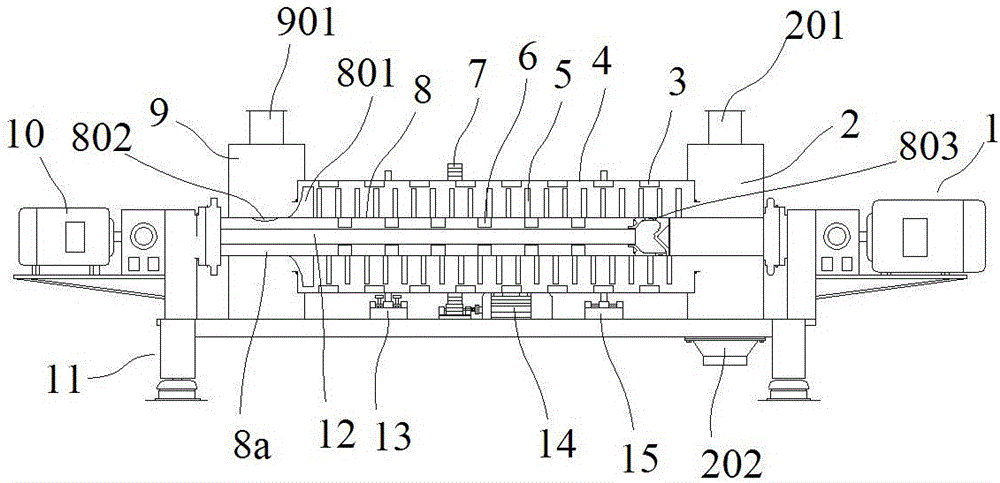
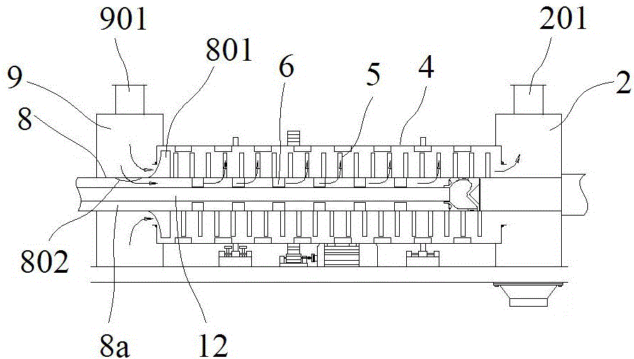
[0021] Such as figure 1 In the shown embodiment, a countercurrent sludge drying device includes a drying outer cylinder 4 , a rotor 8 , a feed pipe 12 and a frame 11 . The drying outer cylinder is horizontally arranged on the rack, and one end of the drying outer cylinder is provided with an air inlet chamber 9, and the other end is provided with a settling chamber 2, and the air inlet chamber and the settling chamber play a supporting role for the drying outer cylinder, while drying The outer cylinder can rotate relative to the air inlet chamber and the settling chamber. The frame is provided with a retaining wheel 13 at one end of the drying outer cylinder, and a support roller 15 at the other end, which supports and positions the drying outer cylinder and ensures that the drying outer cylinder can rotate smoothly. The outer wall of the dry...


PUM


Abstract

The invention discloses a counter-current sludge anhydration apparatus, which comprises an anhydration outer cylinder, a rotor, an inlet pipe and a frame used for supporting and positioning the anhydration outer cylinder, the anhydration outer cylinder is horizontally arranged, an inlet chamber is arranged at one end of the anhydration outer cylinder, a settling chamber is arranged at the other end, a heat flue gas inlet is arranged at top of the inlet chamber, a moisture flue gas outlet is arranged at top of the settling chamber, a center gas outlet is arranged at center position at one end of the anhydration outer cylinder on the settling chamber, the rotor is arranged in the anhydration outer cylinder, the rotor passes through the center gas outlet, a rotor inner core is arranged on the rotor, a feed inlet is arranged at one end of the rotor close to the settling chamber, a discharge hatch is arranged at bottom of the settling chamber, several stirring push bars are arranged at external surface of the rotor, a circulation interval is provided between the top of the stirring push bar and the inner wall of the anhydration outer cylinder, and a rotor motor capable of driving the rotor to rotate is arranged on the frame. The counter-current sludge anhydration apparatus is capable of effectively performing anhydration processing on sludge, and has the advantages of high anhydration efficiency and good anhydration effect.

Description

technical field [0001] The invention belongs to the technical field of sludge treatment, in particular to a countercurrent sludge drying device. Background technique [0002] A large amount of sludge will be produced in the process of sewage treatment, and the treatment method of these sludges is usually incinerated in a furnace, and the hot flue gas discharged after incineration is about 300 to 400 degrees. Since the initial moisture content of the sludge is about 75% to 85%, the water content is too high to be incinerated. Therefore, before the sludge incineration, the sludge needs to be dried first. After the treatment, the moisture content is greatly reduced. , and then the incineration operation can be carried out. The current sludge drying treatment methods usually adopt centrifugal drying or electric heating. For centrifugal drying, the cost of drying is low, but the degree of water reduction in sludge is limited. After centrifugal treatment, the sludge still has a m...

Claims


Application Information

Patent Timeline
Patent Type & Authority Patents(China)
IPC IPC(8): C02F11/12
Inventor 纪伟勇
Owner ZHEJIANG SANLIAN ENVIRONMENT MACHINERY EQUIP
Why Eureka
Try Eureka