
Electric energy power system for full electric propulsion ship

A power system and electric energy technology, which is applied in the direction of propulsion engine, ship propulsion, propulsion components, etc., can solve the problems of difficult installation of system backup units, high space requirements for electric motor units, and high cost, so as to increase operating efficiency and reliability, High reliability and improved stability

Inactive Publication Date: 2015-09-09
INST OF ELECTRICAL ENG CHINESE ACAD OF SCI
View PDF5 Cites 1 Cited by
  • Summary
  • Abstract
  • Description
  • Claims
  • Application Information

AI Technical Summary

Problems solved by technology

[0010] The purpose of the present invention is to overcome the shortcomings of the existing all-electric propulsion ships, such as high-power power generation, high space requirements for electric motor units, high cost and difficult installation of system backup units, and propose an electric energy power system for ships

Method used


Image

  • Electric energy power system for full electric propulsion ship
  • Electric energy power system for full electric propulsion ship
  • Electric energy power system for full electric propulsion ship

Examples


Embodiment Construction

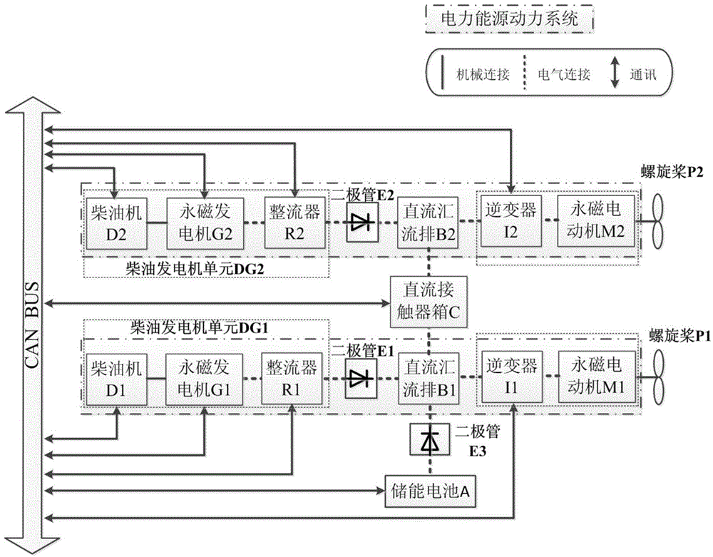
[0052] The electric energy power system for ships of the present invention includes two stand-alone electric energy power systems and a DC contact box C. Two stand-alone electric energy power systems share an energy storage battery A, and the energy storage battery A is connected in parallel with the first DC busbar B1 of the first stand-alone energy power system, and the first DC busbar The positive pole of B1 is connected to the input end of the DC contactor C, and the output end of the DC contactor C is connected to the positive pole of the second DC busbar B2 of the second stand-alone energy power system; the first DC busbar The negative pole of B1 is connected with the negative pole of the second direct current busbar B2 to form a two-machine parallel system.

[0053] The stand-alone electric energy power system is mainly composed of a power generation device, DC busbars B1 and B2, a DC contact box C, an energy storage battery A and a motor drive device.

[0054] The pow...


PUM


Abstract

The invention discloses an electric energy power system for a full electric propulsion ship. The system comprises two single-machine energy power systems and a direct-current contact box (C), wherein the two single-machine electric energy power systems share one energy storage battery (A); the energy storage battery (A) is connected with a first direct-current confluence busbar (B1) of the first single-machine energy power system in parallel; the positive pole of the first direct-current confluence busbar (B1) is connected with the input end of a direct-current contactor (C); the output end of the direct-current contactor (C) is connected with the positive pole of a second direct-current confluence busbar (B2) of the second single-machine energy power system; and the negative pole of the first direct-current confluence busbar (B1) is connected with the negative pole of the second direct-current confluence busbar (B2) to form a double-machine parallel system.

Description

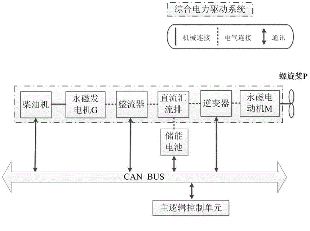
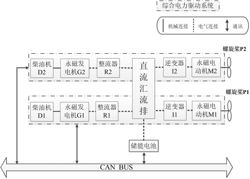
technical field [0001] The invention relates to an electric propulsion system for an all-electric propulsion ship. Background technique [0002] The integrated electric propulsion system of a conventional all-electric propulsion ship includes a single-engine system and a double-engine parallel system, and its structure is as follows: figure 1 and figure 2 as shown, figure 1 and figure 2 Components such as the cooling system, sensors, battery monitoring system, etc. are not shown. [0003] figure 1 It is a schematic diagram of the structure of a conventional integrated electric propulsion system for a stand-alone system. The DC output of the diesel generator set is used for energy confluence in the DC busbar, and the energy is used by the rear-stage motor to drive the propeller system. This scheme belongs to the scheme of a single-machine serial hybrid power system, and the system structure is simple, but the reliability of the system is relatively poor. When a certain...

Claims


Application Information

Patent Timeline
Patent Type & Authority Applications(China)
IPC IPC(8): B63H21/17
Inventor 张剑李金龙温旭辉
Owner INST OF ELECTRICAL ENG CHINESE ACAD OF SCI
Learn More