drilling system

A lifting system, hydraulic drilling rig technology, applied in boring/drilling, drilling/drilling equipment, components of boring machine/drilling machine, etc., can solve the problems of ununiform drilling quality, low production quality, low processing efficiency, etc. , to achieve the effect of improving drilling efficiency, improving stability, and the same feeding force

Active Publication Date: 2017-07-28
宁波千亚照明有限公司
View PDF5 Cites 0 Cited by
  • Summary
  • Abstract
  • Description
  • Claims
  • Application Information

AI Technical Summary

Problems solved by technology

This drilling method needs to be processed one by one, which takes a long time and has low processing efficiency. Moreover, repeated operations on the same workpiece lead to inconsistent drilling quality and low production quality.

Method used


Image

  • drilling system
  • drilling system
  • drilling system

Examples


Embodiment 1

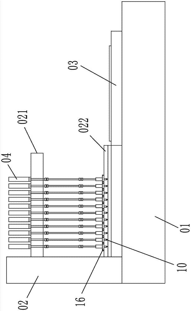
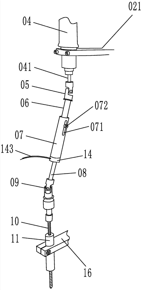
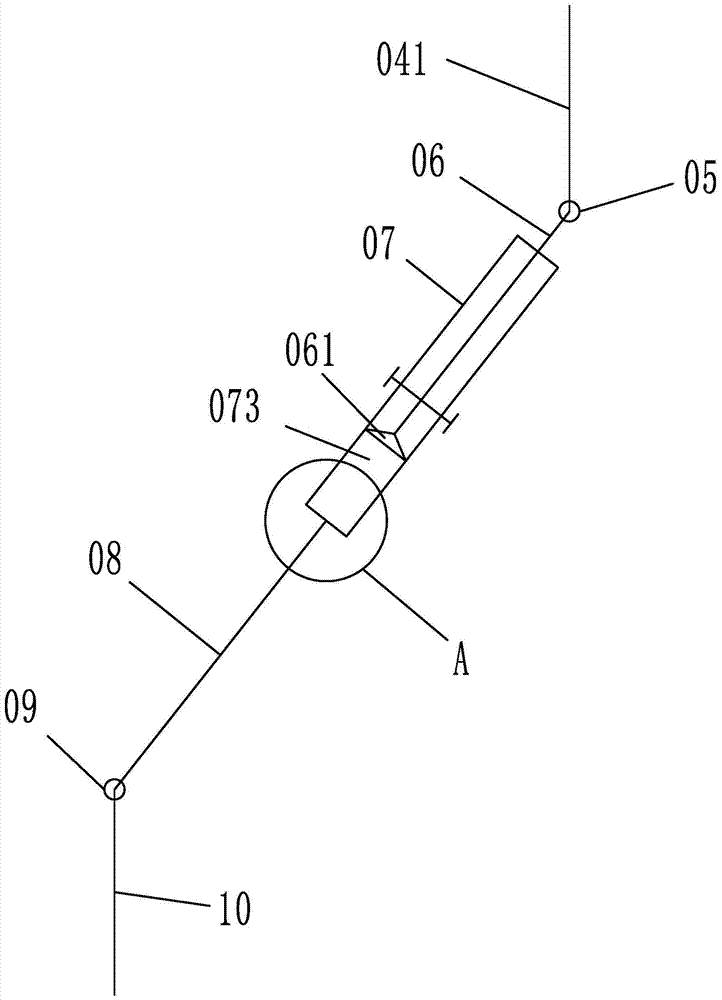
[0022] Embodiment 1: as figure 1 , 2 As shown in .3, a drilling system includes a frame 01, a feeding system 03 and a lifting system 02 are arranged on the frame, an upper lifting frame 021 and a lower lifting frame 022 are connected to the lifting system, and the top of the upper lifting frame is set There are several hydraulic drilling rigs 04 arranged vertically. The driving shaft 041 of the hydraulic drilling rig is connected with the first coupling 05. The angle between the driving shaft of the hydraulic drilling rig and the telescopic shaft is 160°. The lower end of the first coupling is connected to There is a telescopic shaft, the lower end of the telescopic shaft is connected with a connecting shaft 08, the lower end of the connecting shaft is connected with a second coupling 09, the lower end of the second coupling is connected with a drill bit 10, and the outer sleeve of the drill bit is provided with a positioning sleeve 11, and the positioning sleeve Fixed on the...

Embodiment 2

[0024] Embodiment 2: The structure of this embodiment is basically the same as that of Embodiment 1, the difference is that, as Figure 9 As shown, there are five pulse gas charging holes 075 on the lower end surface of the fixed shaft. The pulse gas inlet holes are distributed in a circular arc. The radius length of the air intake cavity is the same. One end of the sliding shaft inside the fixed shaft is provided with a piston that matches the diameter of the air chamber. When the gas volume in the air chamber increases, the piston can be pushed to move, thereby realizing the relative movement between the sliding shaft and the fixed shaft, and elongating the telescopic shaft; When the amount of gas in the air chamber decreases, it can attract the movement of the piston, and then shrink the telescopic shaft. The outer sleeve of the connecting shaft is provided with an air intake sleeve, which is connected with the connecting shaft through a rotating bearing. When the connecti...


PUM


Abstract

The invention relates to a tool device, in particular to a hole drilling system. The hole drilling system comprises a rack. A feeding system and an elevating system are arranged on the rack. An upper elevating rack and a lower elevating rack are connected to the elevating system. Multiple longitudinally arranged hydraulic drilling machines are arranged on the top end of the upper elevating rack. The driving shaft of each of the hydraulic drilling machines is connected with a first shaft coupling. The lower end of each of the first shaft coupling is connected with a telescoping shaft. The lower end of each of the telescoping shafts is connected with a connection shaft. The lower end of each of the connection shaft is connected with a second shaft coupling. The lower end of each of the second shaft coupling is connected with a drilling head. A positioning sleeve sleeves the outer side of each of the drilling heads. The positioning sleeves are fixed on the lower elevating rack. Each of the telescoping shafts comprises a sliding shaft connected with the corresponding first shaft coupling and a static shaft sleeving the outer side of the corresponding sliding shaft. A slide groove is arranged in the side wall of each of the static shafts and parallel to axis of the corresponding static shaft. A guide bolt penetrates through each of the slide grooves. The beneficial effects are that the hole drilling system is capable of drilling holes simultaneously in multiple positions; drilling quality is ensured; drilling efficiency is increased; and drilling time is saved.

Description

technical field [0001] The invention relates to a tooling device, in particular to a drilling system. Background technique [0002] Drilling technology is commonly used in machining, but some workpieces need to drill multiple holes, such as the assembly of lamps, it is necessary to drill more than a dozen or even dozens of holes to tap the thread. In the prior art, drilling adopts a drill press or a hand-held drilling tool to drill holes one by one. This drilling method needs to be processed one by one, which takes a long time and has low processing efficiency. Moreover, repeated operations on the same workpiece lead to inconsistent drilling quality and low production quality. Contents of the invention [0003] The present invention mainly aims at the above problems, and provides a drilling system capable of simultaneously drilling multiple positions, ensuring drilling quality, improving drilling efficiency, and saving drilling time. [0004] The purpose of the present i...

Claims


Application Information

Patent Timeline
Patent Type & Authority Patents(China)
IPC IPC(8): B23B39/28B23B47/22
CPCB23B39/28B23Q5/26
Inventor 付德才
Owner 宁波千亚照明有限公司
Why Eureka
Try Eureka