Oil head for blade propeller turbine

An oil receiver and water turbine technology, which is applied in the field of oil receivers of rotary sluice turbines, can solve the problems of poor sealing, low sensitivity of mechanical feedback, difficult installation, etc. Effect

Inactive Publication Date: 2011-05-11
TIANJIN TIRNFR HEAVY HYDROELECTRIC FRCILITY CO LTD
View PDF0 Cites 0 Cited by
  • Summary
  • Abstract
  • Description
  • Claims
  • Application Information

AI Technical Summary

Problems solved by technology

The oil receiver and the operating oil pipe of the traditional rotary paddle turbine have a split structure. Since the operating oil pipe is integrated with the main shaft, a connecting body (such as the front end shaft of the generator, etc.) is needed to connect the oil receiver and the operating oil pipe. The structure Complicated, difficult to install, and not conducive to the determination of length dimensions
Both the oil basin seat and the oil receiver body of the oil receiver adopt casting structure, the manufacturing mold cost is high, and the processing cycle is long; Strengthen the rigidity of the operating oil pipe, and weld several rows of supporting screws between the inner and outer walls of the operating oil pipe. The disadvantages are: poor sealing, easy to leak oil, and the screws do not have a guiding role
The oil receiver of the water turbine uses a pulley as its recovery mechanism, and the motion state of the blades of the water turbine is fed back to the governor through a mechanical feedback system, so the sensitivity of the mechanical feedback is low, and it is not easy to determine the mid-stroke position of the servomotor with the pulley structure , it will also bring some difficulties to the operation and processing

Method used


Image

  • Oil head for blade propeller turbine
  • Oil head for blade propeller turbine
  • Oil head for blade propeller turbine

Examples


Embodiment Construction

[0016] In order to further understand the invention content, characteristics and effects of the present invention, the following examples are given, and detailed descriptions are as follows in conjunction with the accompanying drawings:

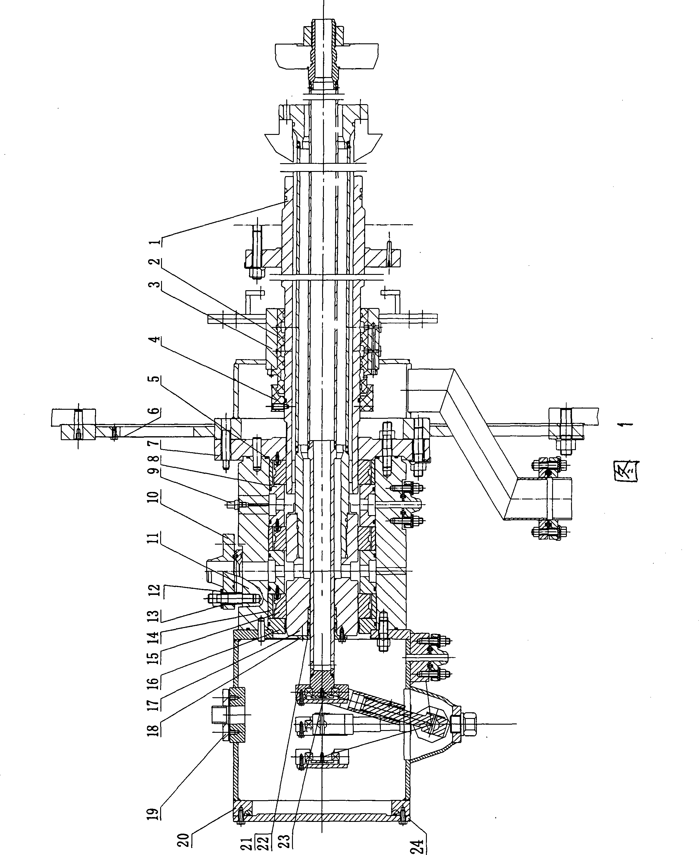
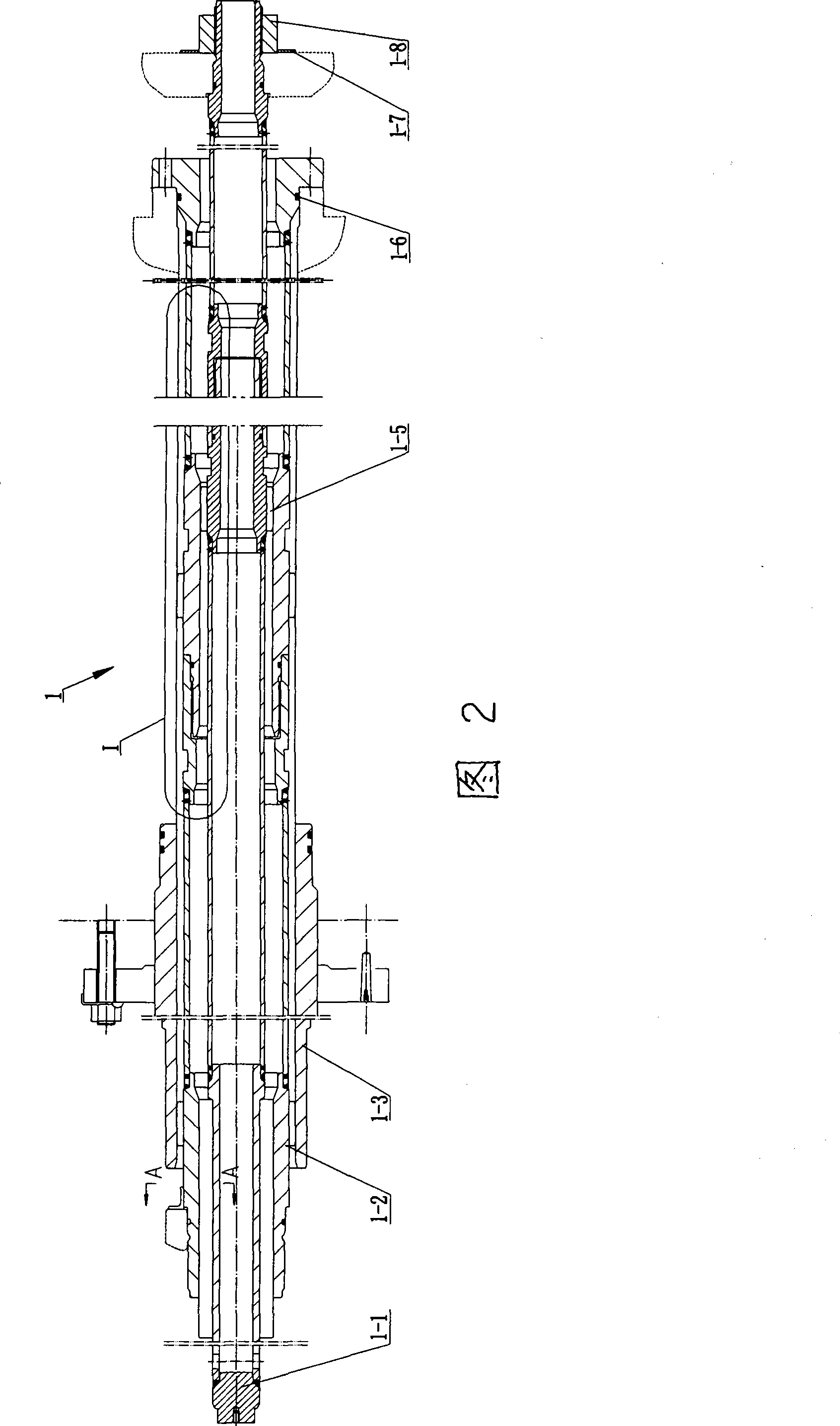
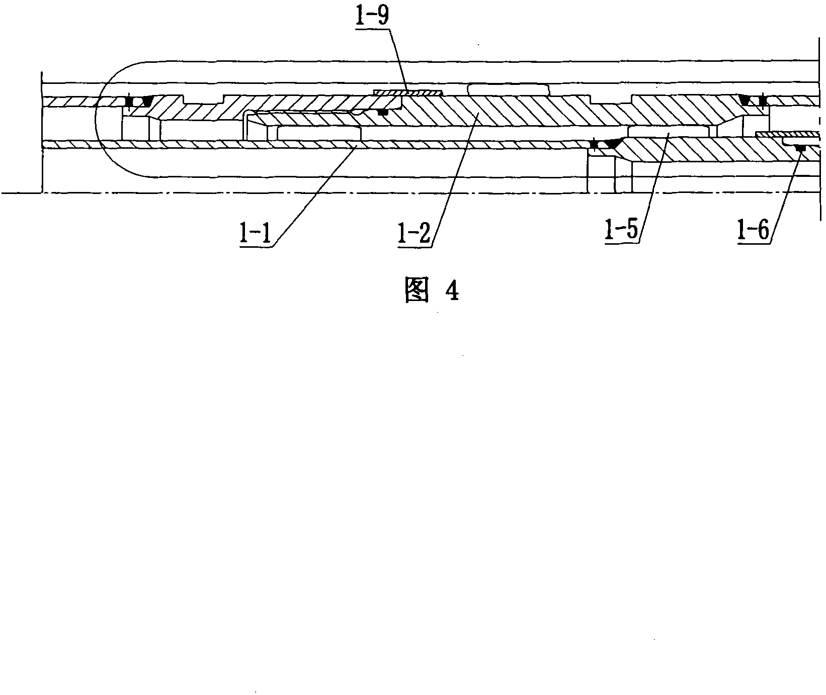
[0017] Please refer to Fig. 1-Fig. 6, the oil receiver of the paddle type turbine mainly includes the operation oil pipe assembly 1, the oil receiver body 11, the front oil tank 20 and the recovery mechanism 23, which consists of the inner pipe 1-1, the middle pipe 1-2 and The operation oil pipe assembly 1 composed of outer pipe 1-3 is connected with the oil receiver body made of seamless steel pipe to form an integral structure, and each section of the pipe body of the operation oil pipe assembly inner pipe, middle pipe and outer pipe is formed by connecting threaded heads. The threaded joints of each section of the pipe body are equipped with limit blocks 1-9 to prevent loosening, and O-rings 1-6 to prevent oil leakage and oil channeling are...


PUM


Abstract

The invention relates to an oil-supply head of a Kaplan type turbine, which comprises an operating oil pipe assembly, an oil-supply head body, a front oil tank and a restoring mechanism; the oil-supply head is characterized in that the operating oil pipe assembly comprising an inner pipe, a middle pipe and an outer pipe is connected with the oil-supply head body which is produced by a seamless steel pipe into a whole structure, the outer wall of the operating oil pipe assembly is sheathed with a sealing pad and a revolving ring, an oil-supply head seat is connected with the oil-supply head body, one end of the oil-supply head body is connected with the front oil tank, the end part of the inner pipe of the operating oil pipe assembly is connected with a swing link type restoring mechanism;all pipe bodies of the operating oil pipe assembly are connected by thread heads, the joint is provided with limited blocks, the outer walls of the inner pipe and the middle pipe of the operating oilpipe assembly are fixedly provided with guide blocks and limited blocks and the oil-supply head seat is a steel plate welded structure. The oil-supply head has the advantages that the outer pipe of the operating oil pipe assembly does not need the supplement of a front-end shaft of a generator, has more simplified structure, is convenient to install and can avoid oil leakage; the restoring mechanism can accurately detect the middle position of the stroke of a vane in virtue of the movement of a fork joint and a swing link, thus leading to more accurate feed back and higher sensitivity.

Description

technical field [0001] The invention belongs to the field of water turbine manufacturing, in particular to an oil receiver of a paddle type water turbine. Background technique [0002] The oil receiver is an important part of the turbine. It is a swivel device that transmits the oil source through the rotating shaft through the fixed casing. It is used to continuously inject the external high-pressure oil into the rotating main shaft through the stationary pipeline system. In the corresponding inlet on the pump, the pressure oil is used to operate the piston mechanism to adjust the rotation of the blades of the turbine, so as to achieve the purpose of adjusting the load of the unit and starting and stopping. The oil receiver and the operating oil pipe of the traditional rotary paddle turbine have a split structure. Since the operating oil pipe is integrated with the main shaft, a connecting body (such as the front end shaft of the generator, etc.) is needed to connect the oi...

Claims


Application Information

Patent Timeline
Patent Type & Authority Patents(China)
IPC IPC(8): F03B11/00F03B15/00
CPCY02E10/20
Inventor 靳环单庆臣
Owner TIANJIN TIRNFR HEAVY HYDROELECTRIC FRCILITY CO LTD
Why Eureka
Try Eureka