Mechanical failure monitoring system and method

A technology of mechanical fault and monitoring system, applied in the field of monitoring, can solve the problems of high power consumption, inability to monitor and analyze various mechanical faults, large equipment size, etc., achieve large frequency bandwidth, get rid of the dependence of CPU processing capacity, and achieve synchronization The effect of analysis and processing

Inactive Publication Date: 2015-09-02
SHENZHEN YATEKS OPTICAL ELECTRONICS TECH CO LTD
View PDF8 Cites 9 Cited by
  • Summary
  • Abstract
  • Description
  • Claims
  • Application Information

AI Technical Summary

Problems solved by technology

However, only one complex algorithm can be implemented in the current window for each calculation, and multiple algorithms are implemented through serial, and simultaneous analysis of multiple channels and synchronous processing of multiple complex algorithms cannot be performed, so the machine cannot be processed at the same time. Perform various fault monitoring and analysis
[0005] The third type is a monitoring system based on a high-performance server (generally an SMP multi-processor structure). This system has dozens of x86 processing cores with strong performance, so it can process multiple channels and multiple algorithms at the same time. However, the whole set of equipment is bulky and consumes a lot of power. It is generally used in online systems and placed in the monitoring room.
Although there is also research on CPU-GPU cooperative computing methods, they are only some basic assumptions mainly aimed at the cooperative mode, and there is no research application in the field of mechanical fault diagnosis.

Method used


Image

  • Mechanical failure monitoring system and method
  • Mechanical failure monitoring system and method
  • Mechanical failure monitoring system and method

Examples


Embodiment 1

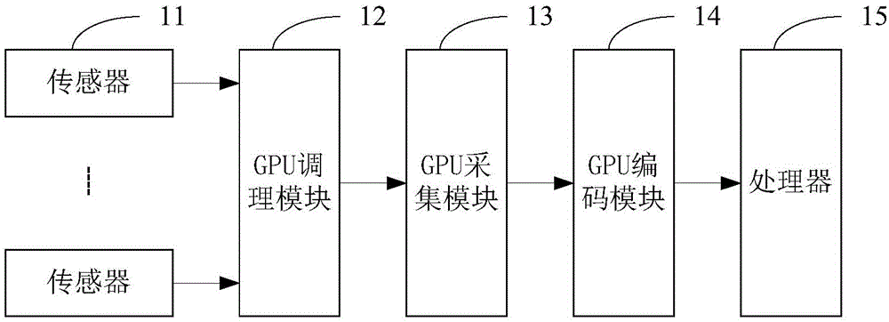
[0042] figure 1 The composition structure of the mechanical fault monitoring system provided by Embodiment 1 of the present invention is shown, and for the convenience of description, only the parts related to the present invention are shown.

[0043] In this embodiment, the low processing capability of the micro-x86 platform CPU is compensated by the GPGPU technology of the general-purpose computing image processor, and a multi-channel miniaturized mechanical fault monitoring system based on GPGPU is provided.

[0044] Such as figure 1 As shown, the mechanical failure monitoring system includes:

[0045] A plurality of sensors 11 are used to respectively detect operating parameters of mechanical equipment to obtain multi-channel operating parameters, and send the multi-channel operating parameters to the GPU conditioning module.

[0046] In this embodiment, the multiple sensors respectively detect operating parameters such as rotational speed, noise, displacement, and vibra...

Embodiment 2

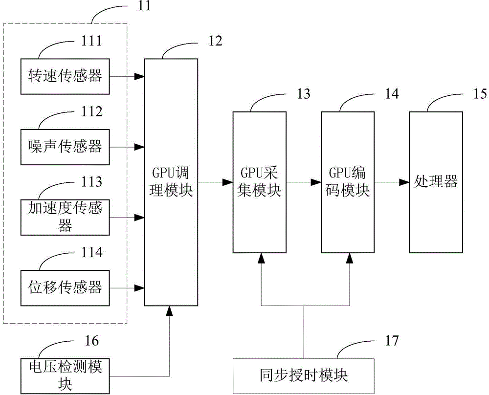
[0063] figure 2 The composition structure of the mechanical fault monitoring system provided by Embodiment 2 of the present invention is shown, and for the convenience of description, only the parts related to the present invention are shown.

[0064] Such as figure 2 As shown, the mechanical failure monitoring system includes:

[0065] A plurality of sensors 11 are used to respectively detect the operating parameters of the machine to obtain multi-channel operating parameters, and send the multi-channel operating parameters to the GPU conditioning module.

[0066] In this embodiment, the multiple sensors include a rotational speed sensor 111, a noise sensor 112, a displacement sensor 113, and an acceleration sensor 114 to detect operating parameters such as rotational speed, noise, displacement, and acceleration of the mechanical equipment during operation; Mechanical equipment for rotors or bearings can also detect the speed and axis trajectory of the rotor or shaft. Af...

Embodiment 3

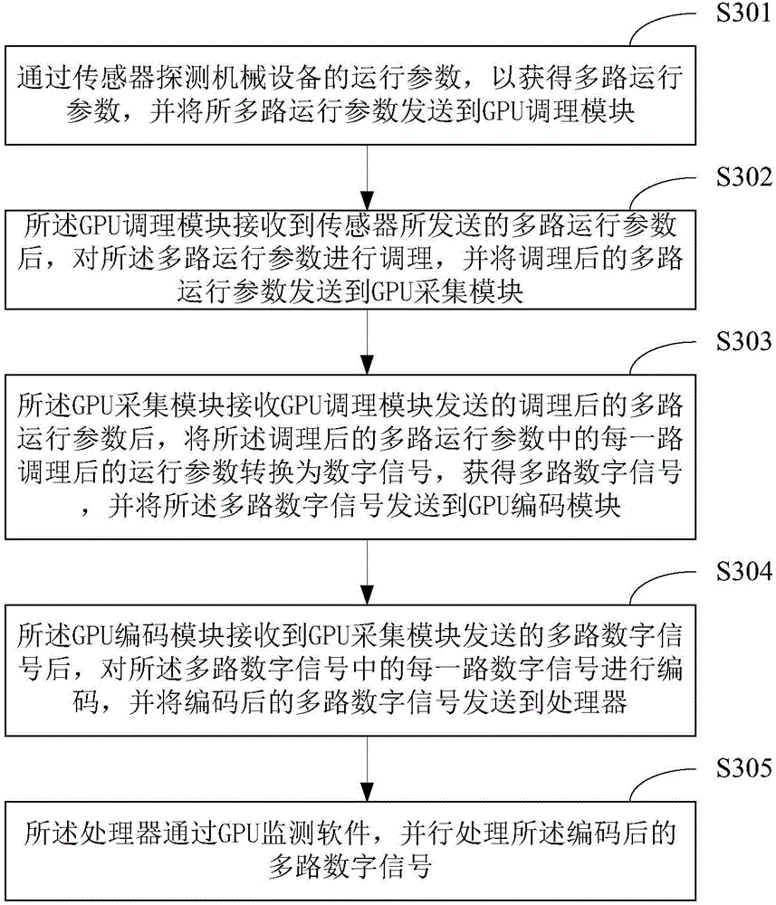
[0085] image 3 The implementation flow of the mechanical failure monitoring method provided by the third embodiment of the present invention is shown.

[0086] The method is applied to figure 1 or figure 2 In the mechanical failure monitoring system described in the embodiment, the system includes a plurality of sensors, a GPU conditioning module, a GPU acquisition module, a GPU encoding module and a processor.

[0087] Such as image 3 As shown, the method includes:

[0088] In step S301, the sensor detects the operating parameters of the mechanical equipment to obtain multiple operating parameters, and sends the multi-channel operating parameters to the GPU conditioning module.

[0089] In this embodiment, the sensors can be speed sensors, noise sensors, displacement sensors and acceleration sensors to detect operating parameters such as speed, noise, displacement and vibration of mechanical equipment during operation; for machines with rotors or bearings The equipmen...


PUM


Abstract

The invention belongs to the field of monitoring technology, and provides a mechanical failure monitoring system and a mechanical failure monitoring method. The mechanical failure monitoring system comprises a plurality of sensors, a GPU conditioning module, a GPU acquisition module, a GPU encoding module and a processor, wherein the plurality of sensors are used for detecting mechanical equipment to obtain multi-path operating parameters; the GPU conditioning module is connected with the plurality of sensors, and is used for conditioning the multi-path operating parameters; the GPU acquisition module is connected with the GPU conditioning module, and is used for converting the conditioned multi-path operating parameters into digital signals to obtain multi-path digital signals; the GPU encoding module is connected with the GPU conditioning module, and is used for encoding the multi-path digital signals; and the processor is connected with the GPU encoding module, and is used for carrying out parallel processing on the encoded multi-path digital signals through GPU monitoring software. Therefore, the purpose of applying a general purpose computation graphics processing unit GPGPU to the mechanical failure monitoring system is realized, the synchronous analysis and processing of the multi-path operating parameters in the current window are realized, the miniaturization of the mechanical failure monitoring system is achieved, and the failure monitoring speed is increased.

Description

technical field [0001] The invention belongs to the technical field of monitoring, and in particular relates to a mechanical fault monitoring system and method. Background technique [0002] With the development of diagnostic monitoring technology, there are many equipments on the market that monitor the operation of machinery and equipment, such as vibration analyzers, noise analyzers, etc. These monitoring instruments are generally composed of acquisition equipment, sensors, processing modules and software, and are mainly divided into three types. [0003] The first type is a basic measurement device that is handheld. Simple output display with one or two sensors, combined with basic conditioning circuitry, using basic analog-to-digital converters and microprocessors. [0004] The second type is a portable instrument based on ARM or x86 processor embedded system design. Compared with the first type of instrument, its data processing ability is stronger, and it can perfo...

Claims


Application Information

Patent Timeline
Patent Type & Authority Applications(China)
IPC IPC(8): G01M99/00
Inventor 马天悦曾佳卢汀肖虎林少明
Owner SHENZHEN YATEKS OPTICAL ELECTRONICS TECH CO LTD
Why Eureka
Try Eureka