
A kind of driving device for the temperature measuring instrument on the outer wall of the cracking furnace tube

A technology of driving device and cracking furnace, which is applied to measuring devices, instruments, scientific instruments, etc., can solve the problems of severe disturbance, large thermal radiation of fire observation holes, small fire observation holes, etc., and achieve synchronous speed control and accurate positioning. Effect

Active Publication Date: 2017-11-10
GUANGDONG UNIV OF PETROCHEMICAL TECH
View PDF1 Cites 1 Cited by
  • Summary
  • Abstract
  • Description
  • Claims
  • Application Information

AI Technical Summary

Problems solved by technology

[0005] 1. The fire viewing hole is small, and the range of the furnace that can be clearly observed is relatively limited
[0006] 2. The working environment is harsh: the furnace has large fireworks and high temperature (up to 1200°C), the heat radiation of the fire observation hole is large, the temperature measurement environment is high in temperature, accompanied by vibration and noise, and the temperature measurement environment is harsh
[0007] 3. Difficult positioning of the furnace tubes: the arrangement of the furnace tubes is irregular, the tubes are sometimes dense and sometimes sparse, and there are occasional front and rear occlusions, accompanied by slight shaking, so it is difficult to locate accurately
[0008] 4. It is difficult to distinguish the temperature measurement value: it is very difficult to identify whether the measured temperature is the temperature of the inner wall of the furnace or the outer wall of the furnace tube, and which furnace tube is the temperature of.
[0009] 5. Furnace pyrotechnics greatly disturb the infrared temperature measurement, and it is very difficult to construct a nonlinear compensation model
[0010] 6. After long-term operation and multiple inspections of the cracking furnace, the thickness of the fire viewing hole, the distance from the fire viewing hole to the furnace tube, the shape and size of the fire viewing hole have undergone fundamental changes, and the reproducibility is poor.
The current technology teaches the method of controlling the position and speed of the light spot in the case of linear motion and curved motion, such as the Chinese invention patent document named as the control method of the light spot pose in laser quenching with the application number 2005100282901, which discloses A method to control the pose of the light spot, but it is aimed at the curve movement, and the solution is that the scanned object moves while the probe emitting the light spot does not move, which is not suitable for the drive device of the pyrometer on the outer wall of the cracking furnace tube

Method used


Image

  • A kind of driving device for the temperature measuring instrument on the outer wall of the cracking furnace tube
  • A kind of driving device for the temperature measuring instrument on the outer wall of the cracking furnace tube
  • A kind of driving device for the temperature measuring instrument on the outer wall of the cracking furnace tube

Examples


Embodiment

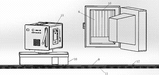
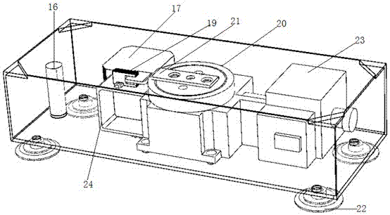
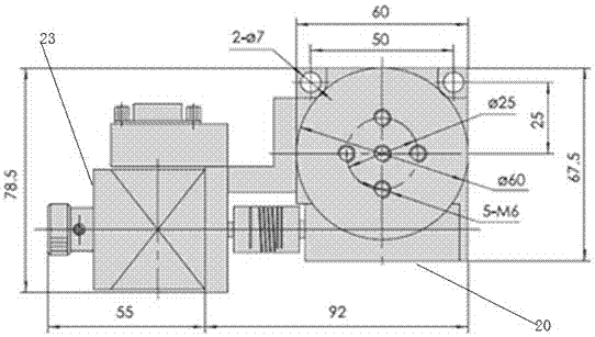
[0039] Such as figure 1 and figure 2As shown, a pyrolysis furnace pipe outer wall pyrometer driving device includes guide rails 9 with grooves on both sides and a temperature measurement drive table 10, racks 11 and magnets 12 are installed on the guide rails 9, and the measuring The temperature driving table 10 comprises a base plate, four guide wheels 22 embedded in the grooves of the guide rail 9 are installed below the base plate, and a horizontal drive motor 17, a rotary drive motor 23, a Hall switch 16 and a photoelectric drive are installed on the base plate. The switch 19, the horizontal driving motor 17 is connected with the gear, and is used to drive the temperature measurement driving platform 10 to move along the rack 11 on the guide rail 9, and the rotary driving motor 23 is connected to the rotator 20, and the rotator is installed There is a baffle 21, and the speed of the horizontal drive motor 17 and the angular velocity of the rotary drive motor 23 satisfy t...


PUM


Abstract

The invention discloses a driving device for a temperature measuring instrument on the outer wall of a cracking furnace tube, which includes a guide rail with grooves on both sides and a temperature measurement drive platform. A rack is installed on the guide rail, and the temperature measurement drive platform includes a bottom plate. A number of guide wheels embedded in the groove of the guide rail are installed under the base plate. A horizontal drive motor and a rotary drive motor are installed on the base plate. The horizontal drive motor is connected with the gear and is used to drive the temperature measurement drive table The bar moves on the guide rail, the rotary drive motor is connected with the rotator, the speed of the horizontal drive motor and the angular velocity of the rotary drive motor satisfy the following relationship: where, ω is the speed of the rotary drive motor, and V1 is the speed of the horizontal drive motor , H1 is the distance between the guide rail plane and the cracking furnace tube plane, H2 is the distance between the guide rail plane and the cracking furnace fire viewing hole, and H3 is the depth of the cracking furnace fire viewing hole. The invention realizes the two-phase movement of the temperature measuring instrument, so that the temperature measuring instrument can uniformly scan all the furnace tubes.

Description

technical field [0001] The invention relates to the field of petrochemical industry, in particular to a driving device for a pyrometer on the outer wall of a cracking furnace tube. Background technique [0002] The ethylene industry is an important substrate in the petrochemical industry, and the cracking process is one of the key technologies in the ethylene industry. At present, more than 99% of my country's ethylene production uses tube furnace steam pyrolysis technology, and the operating status of the cracking furnace directly affects the yield and quality of ethylene. In the cracking furnace, the furnace tube is the key component, which plays the role of heating the raw material and the reactor. Since the furnace tube of the cracking furnace operates in a high-temperature complex environment for a long time, it is prone to surface oxidation, coking caused by corrosion, local over-temperature, etc., as well as phase change and mechanical performance degradation caused ...

Claims


Application Information

Patent Timeline
Patent Type & Authority Patents(China)
IPC IPC(8): G01J5/02
Inventor 彭志平
Owner GUANGDONG UNIV OF PETROCHEMICAL TECH
Learn More