
High-stiffness guide structure

A guiding structure, high rigidity technology, applied in the direction of linear motion bearings, bearings, shafts and bearings, etc., to ensure the stability and reliability of load, simple structure, and reliable guiding performance.

Inactive Publication Date: 2015-09-02
CHINA NAT HEAVY MACHINERY RES INSTCO
View PDF7 Cites 4 Cited by
  • Summary
  • Abstract
  • Description
  • Claims
  • Application Information

AI Technical Summary

Problems solved by technology

[0003] In order to overcome the above-mentioned shortcoming of prior art, the object of the present invention is to provide a kind of guide structure of high rigidity, can solve heavy load and unbalanced load occasion to the high rigidity on the vertical motion direction and the low motion resistance requirement on the motion direction. question

Method used


Image

  • High-stiffness guide structure
  • High-stiffness guide structure
  • High-stiffness guide structure

Examples


Embodiment Construction

[0013] The implementation of the present invention will be described in detail below in conjunction with the drawings and examples.

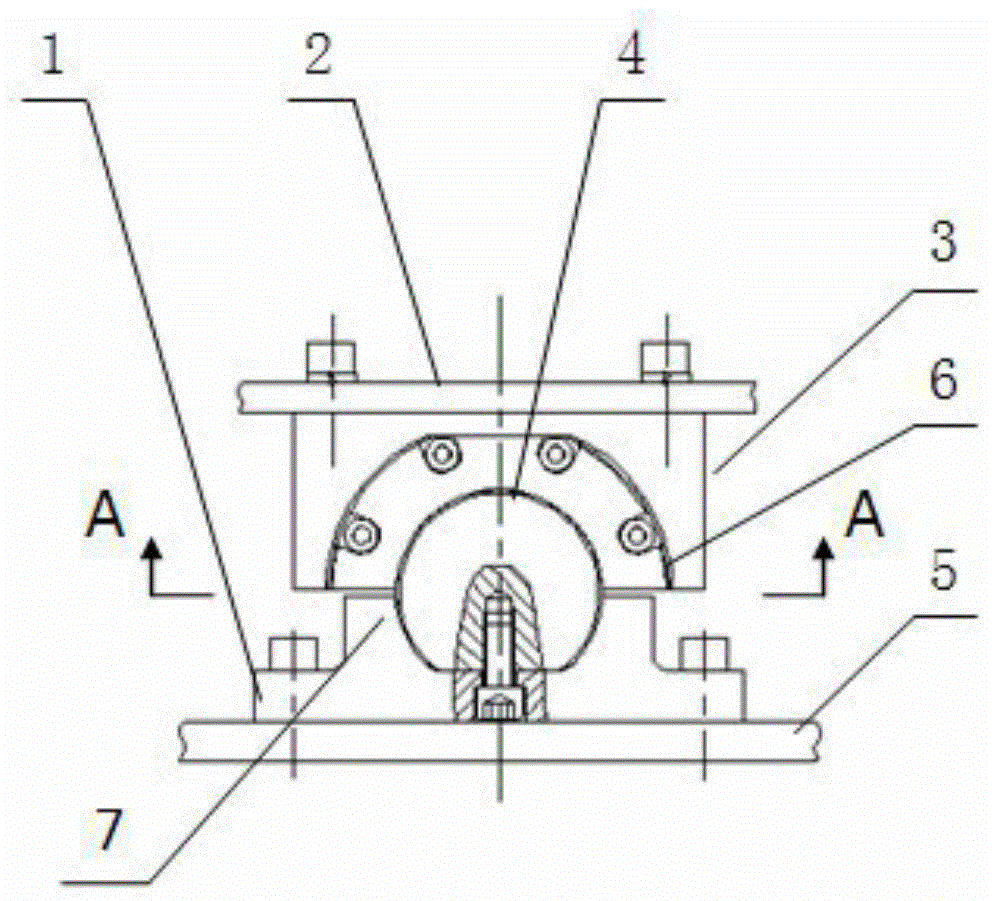
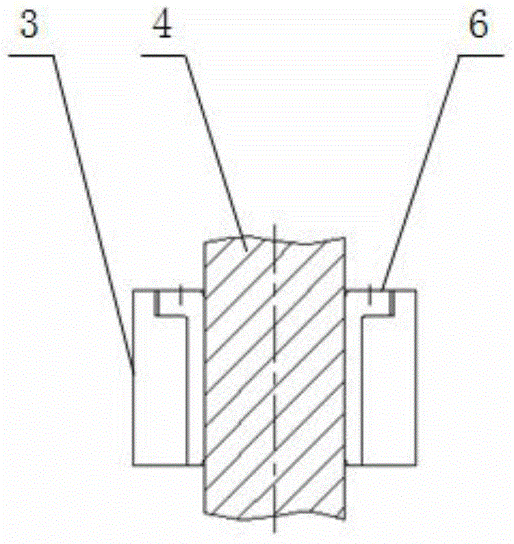
[0014] like figure 1 , figure 2 as well as image 3 As shown, a high-rigidity guide structure includes an optical axis 4, and the optical axis 4 is used as a guide shaft, and the reliability of fixing needs to be ensured to prevent its rotation and axial slippage. Specifically, a certain number of evenly distributed threaded holes are processed along the axial centerline on the rectangular section formed after the longitudinal section from the axial eccentricity of the optical axis 4, and the longitudinal section is connected with the support of the shaft support 1 The surfaces are fitted together and locked by screws, so as to avoid the rotation and axial slippage of the optical axis 4, and ensure the stability of the guiding process of the moving part 2. There are boss structures 7 on both sides of the support surface of the shaft support ...


PUM


Abstract

The invention provides a high-stiffness guide structure. The high-stiffness guide structure comprises an optical shaft; the longitudinal section of the optical shaft is locked on the supporting surface of a shaft support by use of a screw; a plurality of sliders mounted at the bottom of a moving part are in fit with the surface of the optical shaft by use of guide sleeves inlaid into the sliders, and therefore, efficient and reliable guide motion of the moving part in the axial direction of the optical shaft is realized. The high-stiffness guide structure is simple in structure, easy to manufacture, simple and convenient to mount, and capable of bearing relatively high loads in the radial direction of the guide shaft, has efficient and reliable guide performance, and is especially suitable for heavy loading and unbalance loading, in particular occasions of great radial loads.

Description

technical field [0001] The invention belongs to the technical field of guiding structures, in particular to a high-rigidity guiding structure. Background technique [0002] The main function of the guide is to provide guidance for the movement mechanism. In some occasions, especially for some heavy machinery, the guide device also needs to bear a certain load perpendicular to the direction of motion, so the guide device is required to have higher stiffness in the direction of vertical motion. Most of the more mature guide mechanisms are difficult to meet the above requirements. The common solution is to use copper plates as guide elements in the bearing direction, and use the high lubricity of the copper plates and the high stiffness of the guide plane to ensure the reliability of the guide mechanism. However, the installation space of the planar guide mechanism is large, the structure is difficult to compact, the manufacturing cost is high, and the installation and adjustm...

Claims


Application Information

Patent Timeline
Patent Type & Authority Applications(China)
IPC IPC(8): F16C29/02
Inventor 张峻荆云海董晓娟王哲琳张立波邱立朋
Owner CHINA NAT HEAVY MACHINERY RES INSTCO
Learn More