
Stope debris flow treatment method in caving mining method and device thereof

A caving mining and debris flow technology, applied in safety devices, ground mining, mining equipment and other directions, can solve the problems of treating symptoms but not the root cause, low efficiency and high cost, and urgent problems of caving stope debris flow control, so as to reduce costs and reduce costs. , the effect of improving efficiency and resource recovery rate

Active Publication Date: 2015-09-02
CENT SOUTH UNIV
View PDF6 Cites 2 Cited by
  • Summary
  • Abstract
  • Description
  • Claims
  • Application Information

AI Technical Summary

Problems solved by technology

[0004] A large number of literature searches found that effective debris flow control methods in stopes have not yet been found, and more mining methods with low efficiency and high cost are used, or methods that treat symptoms but not the root cause, such as setting intercepting ditches on the surface to prevent surface water from reaching the stope , or do a good job of protecting the surface vegetation, or blocking the hydraulic communication channel, etc., these methods are difficult to fundamentally solve the problem of debris flow in the stope, so the problem of debris flow control in the caving method is urgent

Method used


Image

  • Stope debris flow treatment method in caving mining method and device thereof
  • Stope debris flow treatment method in caving mining method and device thereof
  • Stope debris flow treatment method in caving mining method and device thereof

Examples


Embodiment Construction

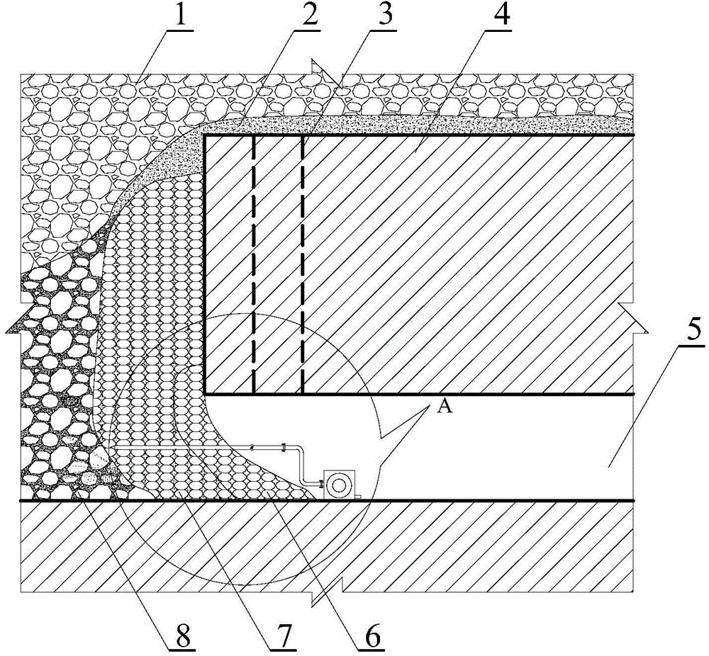
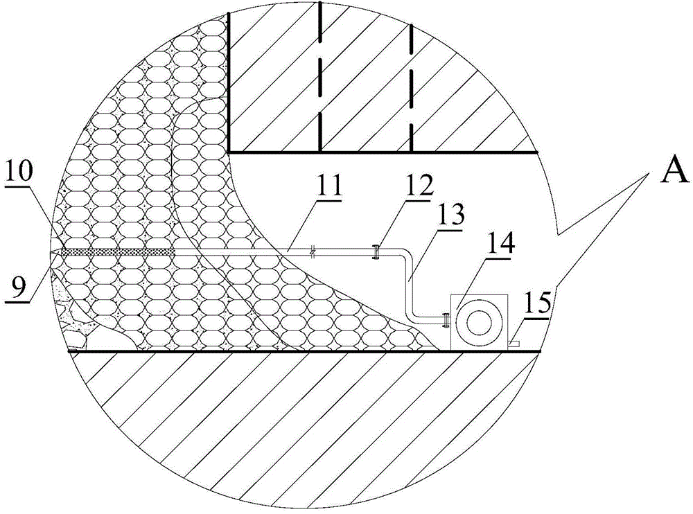
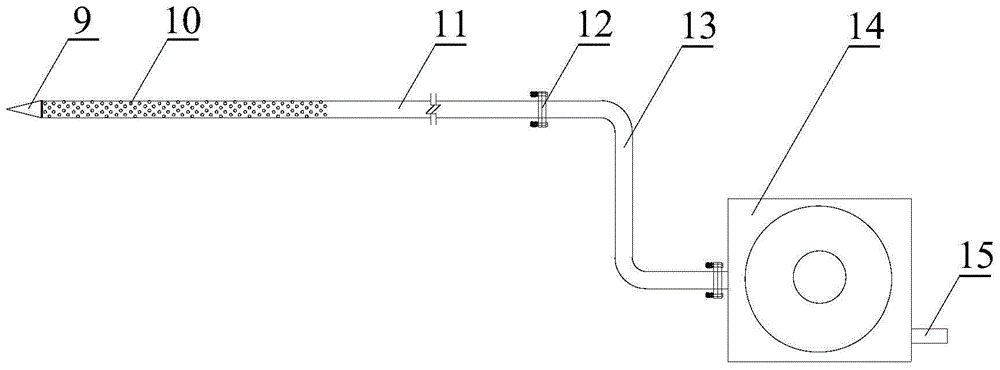
[0028] The present invention will be further described below in conjunction with the accompanying drawings and specific embodiments.

[0029] see figure 1 , figure 2 , image 3 and Figure 4 The mud pump 14 is provided with a drain port 15, and the inlet end of the mud pump 14 is connected with a water filter steel pipe 11 through a rigid flange 12. water hole 10. The main body of the water filter steel pipe 11 is a seamless steel pipe with an outer diameter of Φ100-150mm, a wall thickness of δ5mm-8mm, and a length of 6-8m. flange12.

[0030] The length of cone 9 is 2 times of the diameter of water filter steel pipe 11, and diameter is identical with water filter steel pipe 11 diameters.

[0031] The front end 1m-2m of the water-filtering steel pipe 11 is drilled with a drill to drill some of the above-mentioned water-filtering holes 10 with a diameter of Φ10mm-20mm. The several water-filtering holes 10 are arranged in a quincunx shape, and the area of ​​the several wat...


PUM


Abstract

The invention discloses a stope debris flow treatment method in a caving mining method and a device of the method. In a stope ore discharge opening position of the caving mining method, before the stope ore discharge, an impact device is used for beating a water filtering steel pipe into a caving ore pile with the debris flow harm; water filter holes are uniformly distributed in the insertion front end of the water filtering steel pipe; the tail end of the water filtering steel pipe is connected with the suck-in end of a slurry pump through a rigid flange; the slurry pump is started; the blockage of the water filtering pipeline by debris flow slurry in the ore pile is eliminated through the negative pressure influence and the vibration effect exerted on the water filtering pipeline by the slurry pump; slurry and water in the ore pile is discharged as fast as possible; then, the impact device is continuously used for beating the water filtering steel pipe into a deeper position, with the debris flow damage, of the ore pile; slurry is discharged by the slurry pump; the operation is circulated in such a way until the slurry quantity in the stope ore pile is greatly reduced; the stope debris flow damage is eliminated. The method has the advantages that the operation is simple and convenient; the pipe blockage probability by mud and stones is low; the water discharge and mud discharge speed is high; the stope debris flow treatment effect is good; the water filtering steel pipe can be cyclically used, and the like.

Description

technical field [0001] The invention relates to a method for controlling mud-rock flow in a stope, in particular to a method for controlling mud-rock flow in a caving mining method. The invention also relates to a device for realizing the control method of the stope debris flow in the caving mining method. Background technique [0002] Caving mining method is a mining method that controls and manages stope pressure through caving surrounding rocks. Due to the advantages of simple stope process structure, high degree of mechanization, large production capacity, safe operation, and low mining cost, it is still widely used at home and abroad. It has been widely used in metal and non-metal mines. [0003] Caving method mining is characterized by relying on medium and deep holes to drop ore. The caving ore is discharged through the bottom structure or the roadway end scraper. The purpose of dealing with gobs and controlling ground pressure activities. The caving method has goo...

Claims


Application Information

Patent Timeline
Patent Type & Authority Applications(China)
IPC IPC(8): E21C41/16E21F16/00
Inventor 赵国彦林春平候俊刘希灵刘志祥
Owner CENT SOUTH UNIV
Learn More