
Magnetron sputtering coating equipment

A magnetron sputtering coating and equipment technology, applied in sputtering coating, ion implantation coating, vacuum evaporation coating, etc., can solve the adverse effects of process repeatability, inability to achieve coating, air pressure fluctuations and other problems, to achieve The thickness of the coating is kept uniform, the effect of solving the uneven thickness of the coating and reducing the fluctuation of air pressure

Active Publication Date: 2015-09-02
ANHUI CHUNYUAN COATING TECH CO LTD
View PDF8 Cites 8 Cited by
  • Summary
  • Abstract
  • Description
  • Claims
  • Application Information

AI Technical Summary

Problems solved by technology

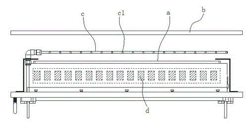
However, this design has major defects: firstly, the gas injection method in front of the target will cause pressure fluctuations on the surface of the target a, which will have an adverse effect on the repeatability of the process; secondly, it is impossible to achieve a large area of ​​uniform coating , after the evenly distributed argon ions near the target a bombard the surface of the target a, the target particles are sputtered and fly to the surface of the substrate b, and the flight direction of a large number of sputtered target particles obeys the cosine distribution, as figure 2 As shown, the thickness of the film facing the center of the target a is greater than that at both ends

Method used


Image

  • Magnetron sputtering coating equipment
  • Magnetron sputtering coating equipment
  • Magnetron sputtering coating equipment

Examples


Embodiment Construction

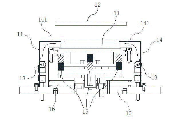
[0016] like Figure 4 As shown, a magnetron sputtering coating equipment includes a cathode target 11 horizontally arranged on a base 10, the cathode target 11 is a rectangular plate structure, a substrate 12 is arranged above the cathode target 11, and the cathode target A magnet 15 is arranged under the material 11, and the magnet 15 forms an arched magnetic field on the upper surface of the cathode target 11. The equipment also includes a gas supply unit for blowing an inert gas to the upper surface of the cathode target 11. The gas supply unit includes The gas supply pipeline arranged along the length direction of the cathode target, the gas supply pipeline 13 is provided with a plurality of air outlet holes 131 at intervals along the tube length direction, and the layout density of the gas outlet holes 131 in the middle section of the gas supply pipeline 13 is smaller than that at both ends , so that the concentration of inert gas in the middle section of the cathode targ...


PUM


Abstract

The invention belongs to the technical field of material surface coatings, and particularly relates to magnetron sputtering coating equipment. The hidden gas circuit design is adopted, inert gases are naturally diffused to the surface of a target material from the edge of the target material, air pressure fluctuation on the surface of the target material is effectively lowered, and repeatability of the coating technology is guaranteed. In addition, the nonequilibrium magnetic field and the compensation gas circuit design are adopted in the equipment, the problem that the coating thickness is uneven due to gas circuit homogenizing and magnetic field homogenizing in an existing structure is effectively solved, and the coating thickness of all areas of a substrate is kept even.

Description

technical field [0001] The invention belongs to the technical field of material surface coating, and in particular relates to a magnetron sputtering coating equipment. Background technique [0002] like figure 1 As shown, the magnetron sputtering coating process uses the coating material as the cathode target a, the material to be coated as the substrate b, and uses argon ions to bombard the target to produce cathode sputtering. In addition, the magnet d is used to cathode A magnetic field is formed on the surface of the target a, and the concentration of charged particles by the magnetic field is used to increase the density of argon ions to increase sputtering rate, the target atoms are sputtered onto the substrate b, and a coating is formed after deposition. The general sputtering method can be used to prepare multiple materials such as metals and insulators, and has the advantages of simple equipment, easy control, large coating area and strong adhesion. like figur...

Claims


Application Information

Patent Timeline
Patent Type & Authority Applications(China)
IPC IPC(8): C23C14/35
Inventor 张心凤郑杰尹辉
Owner ANHUI CHUNYUAN COATING TECH CO LTD
Learn More