
a transfer agency

A conveying channel and conveying device technology, applied in the field of LED chip support transfer equipment, can solve the problems of inability to transfer LED chip supports of various sizes and narrow application range, and achieve flexible adjustment, low labor intensity and high placement efficiency. Effect

Active Publication Date: 2017-03-01
深圳市佳思特光电设备有限公司
View PDF9 Cites 0 Cited by
  • Summary
  • Abstract
  • Description
  • Claims
  • Application Information

AI Technical Summary

Problems solved by technology

[0004] Therefore, the object of the present invention is to overcome the technical defect that the LED chip holder transfer device in the prior art cannot transfer LED chip holders of various specifications and sizes, and thus has a narrow application range, thereby providing a LED chip holder capable of transferring various specifications and sizes. bracket, thus suitable for a wide range of transfer mechanisms

Method used


Image

  • a transfer agency
  • a transfer agency
  • a transfer agency

Examples


Embodiment Construction

[0047] A transfer mechanism provided by the present invention will be further described in detail below in conjunction with the accompanying drawings.

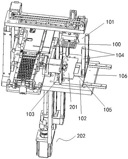
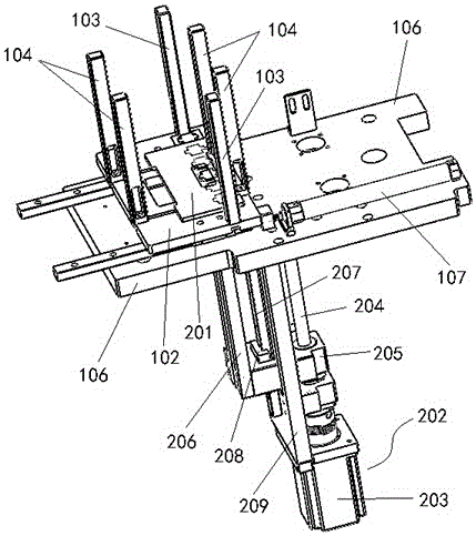
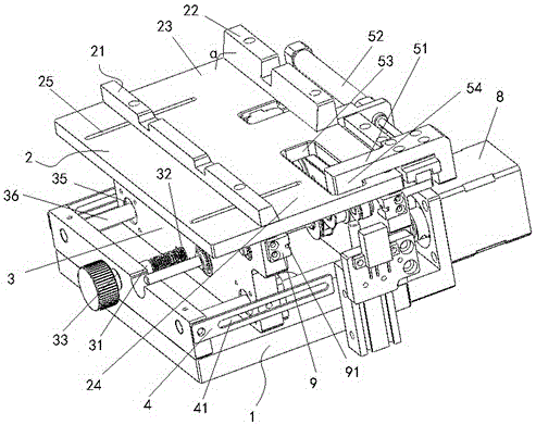
[0048] This embodiment provides a transfer mechanism, such as figure 1 As shown, it includes a material storage device, which has a storage space for placing the object to be transferred 100, and the storage space has an upper opening 101 that can input or output the above-mentioned object to be transferred 100, and is used to drive the to-be-transferred object placed in the above-mentioned storage space. The moving device for transferring the object 100 to move up and down inside the accommodation space is used to clamp the object 100 to be transferred from the position of the upper opening 101 to a certain height by the moving device, and is used to receive the object to be transferred from the gripping device. Objects, and convey the objects to be transferred to the fixture for processing through the conveying channel.

[...


PUM


Abstract

The invention provides a transferring mechanism. The transferring mechanism comprises an accommodating device, a moving device, a clamping device and a conveying device, wherein the accommodating device is provided with an accommodating space, a bottom faceplate and limiting plates, the accommodating with an upper opening is used for accommodating to-be-transferred articles, the limiting plates are mounted on the bottom faceplate to form the accommodating space, and the dimension of the accommodating space can be changed since the limiting plates are movably mounted on the bottom faceplate via mounting structures; the moving device is used for driving the to-be-transferred articles to move in the accommodating space; the clamping device is used for clamping and taking the to-be-transferred articles which are moved to the required height by the moving device; the conveying device is used for receiving the to-be-transferred articles from the clamping device and conveying the to-be-transferred articles to a clamp via a conveying passageway. The transferring mechanism is capable of transferring the to-be-transferred articles in various specifications since the dimension of the accommodating space can be adjusted at any time according to the size of the to-be-transferred articles, so that an application range of the transferring mechanism is enlarged.

Description

technical field [0001] The invention relates to a transfer mechanism, which belongs to the technical field of LED chip support transfer equipment. Background technique [0002] In the traditional chip manufacturing process, for the loading and unloading operations of chip holders such as LEDs, the LED chip holders are usually manually put into the standard material box one by one, and then the LED chip holders are pushed into the fixture by the cylinder for processing. The number of LED chip holders placed in the traditional standard material box at one time is small, and the material box needs to be replaced frequently. Moreover, in order to avoid the movement of other adjacent chip holders when the cylinder pushes the chip holder, it is also necessary to replace the two adjacent LED chip holders. There is a gap between them, which makes manual operation time-consuming and labor-intensive. [0003] Chinese patent document CN202662661U discloses a LED chip support transfer ...

Claims


Application Information

Patent Timeline
Patent Type & Authority Patents(China)
IPC IPC(8): B65H5/08B65H5/16H01L21/677
Inventor 徐大林杨华
Owner 深圳市佳思特光电设备有限公司
Learn More