Driving device of steel ladle sliding nozzle mechanism

A technology of sliding nozzle and driving device, which is applied to casting melt containers, metal processing equipment, casting equipment, etc., can solve problems such as cost increase, steel leakage, affecting the service life of refractory materials, etc., so as to improve service life and avoid swinging up and down. , the effect of preventing steel leakage

Inactive Publication Date: 2015-09-02
HANDAN TAIHE METALLURGICAL MACHINERY
View PDF7 Cites 2 Cited by
  • Summary
  • Abstract
  • Description
  • Claims
  • Application Information

AI Technical Summary

Problems solved by technology

The current side drive form makes the connecting rod a swing up and down during the movement of the hydraulic cylinder. This up and down swing will affect the use of the mechanism and affect the stability of the refractory surface pressure in the mechanism. , affecting the service life of refractory materials, the cost will increase, and there will be a certain risk of steel breakout

Method used


Image

  • Driving device of steel ladle sliding nozzle mechanism
  • Driving device of steel ladle sliding nozzle mechanism

Examples


Embodiment Construction

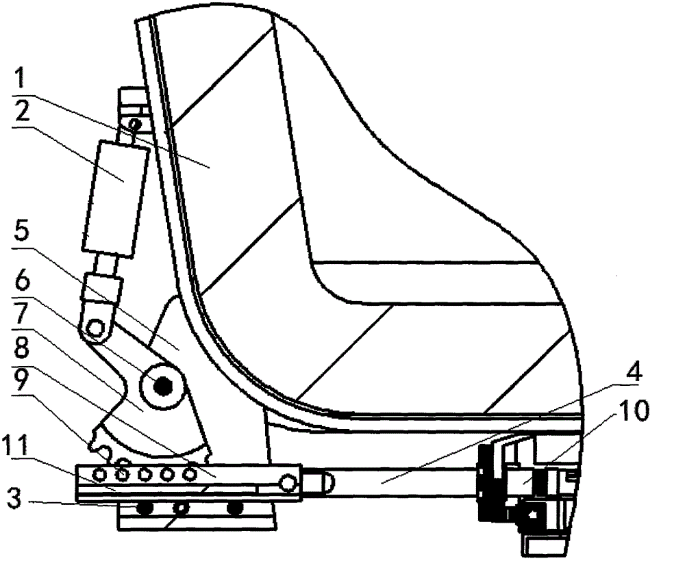
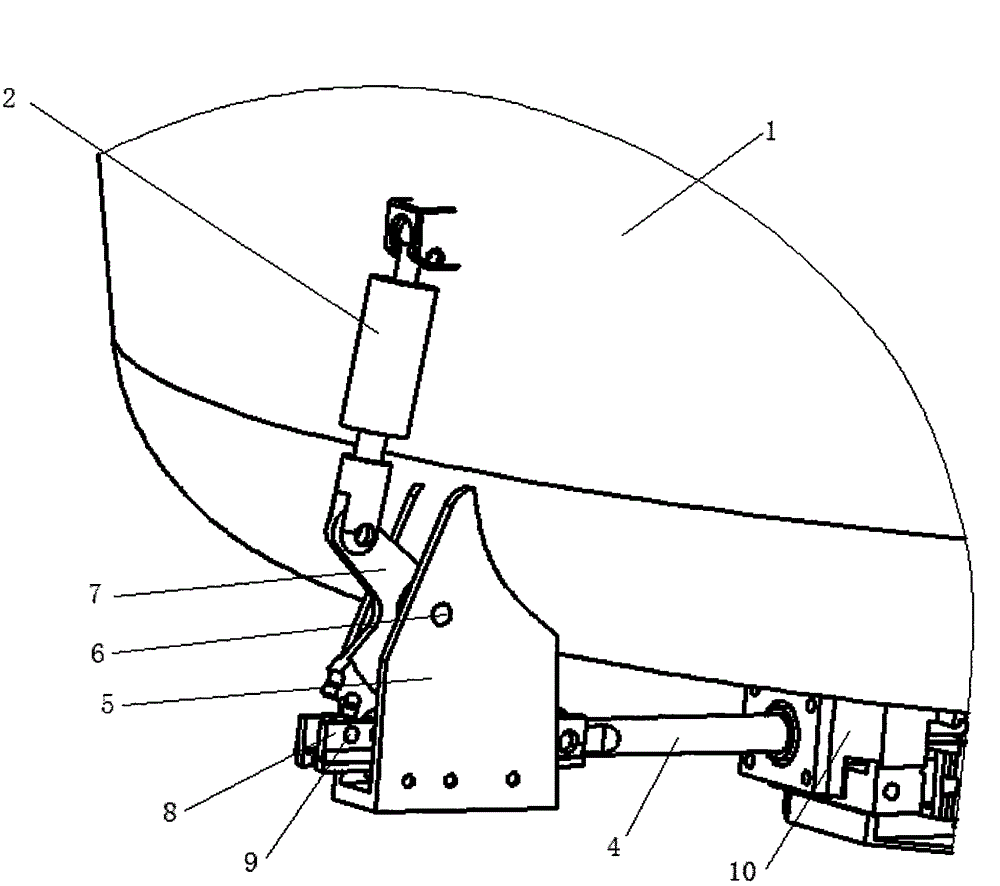
[0011] Such as figure 1 , 2 As shown, a driving device of a ladle sliding nozzle mechanism of the present invention includes a bracket 5 fixed on the ladle 1, the bracket 5 is a U-shaped structure, and the bottom of the bracket 5 is provided with a plurality of rotating shafts 3, the A shaft sleeve is provided between the rotating shaft 3 and the support 5; a sprocket 7 is hinged through a pin 6 in the middle of the support 5, and a hydraulic cylinder 2 is connected to the sprocket 7, and the hydraulic cylinder 2 is rotatably installed on the ladle 1 on;

[0012] A chain groove 8 is provided above the rotating shaft 3, a chain 11 is provided below the chain groove 8, and a plurality of roller shafts 9 are arranged on the top of the chain groove 8, and rollers are arranged on the roller shaft 9. The sprocket 7 passes through the roller and cooperates with the chain 11;

[0013] One end of the chain groove 8 is fixed to the connecting rod 4 , and the free end of the connectin...


PUM


Abstract

The invention provides a driving device of a steel ladle sliding nozzle mechanism. According to the driving device, vertical swinging of a connecting rod is avoided. The driving device comprises a support fixed to a steel ladle. The support is of a U-shaped structure. A plurality of rotating shafts are arranged at the bottom of the support. A shaft sleeve is arranged between the rotating shafts and the support. A chain wheel is hinged to the middle of the support through a pin shaft. An air cylinder is connected to the chain wheel and rotatably installed on the steel ladle. A chain groove is formed above the rotating shafts. A chain is arranged at the lower portion of the chain groove. A plurality of roller shafts are arranged at the upper portion of the chain groove. Rollers are arranged on the roller shafts. The chain wheel penetrates through the rollers to be matched with the chain. A connecting rod is fixed to one end of the chain groove. The free end of the connecting rod is connected with the sliding nozzle mechanism.

Description

technical field [0001] The invention relates to a sliding nozzle device, in particular to a driving device for a ladle sliding nozzle mechanism. Background technique [0002] At present, there are two ways of driving the transmission hydraulic cylinder of the sliding nozzle mechanism used on the steelmaking ladle in China, one is a straight-forward type, and the hydraulic cylinder is installed above the mechanism. The other is the side drive type, and the hydraulic cylinder is installed on the wall of the ladle. Such as figure 1 shown. The current side drive form makes the connecting rod a swing up and down during the movement of the hydraulic cylinder. This up and down swing will affect the use of the mechanism and affect the stability of the refractory surface pressure in the mechanism. , affecting the service life of refractory materials, the cost will increase, and there will be a certain risk of steel breakout. Contents of the invention [0003] The invention prov...

Claims


Application Information

Patent Timeline
Patent Type & Authority Applications(China)
IPC IPC(8): B22D41/38
Inventor 张付会
Owner HANDAN TAIHE METALLURGICAL MACHINERY
Why Eureka
Try Eureka