
SF 6 sealing pot protective device and using method for electric high-pressure oil-filling mutual inductor

An oil-filled transformer and protection device technology, applied in the direction of inductors, transformers/inductor cooling, transformers, etc., can solve problems such as explosion safety, transformer accidents, accidents, etc., to achieve long-term stability of oil quality and ensure safety. The effect of running and protecting oil

Active Publication Date: 2015-08-26
STATE GRID CORP OF CHINA +5
View PDF6 Cites 0 Cited by
  • Summary
  • Abstract
  • Description
  • Claims
  • Application Information

AI Technical Summary

Problems solved by technology

[0002] At present, the sealing protection device of the traditional high-voltage oil-filled transformer for electric power is mainly the protection device of the metal corrugated expander or the gland is tightly sealed. To compensate the pressure change caused by the rise and fall of the oil level in the transformer due to the thermal expansion and contraction of the oil inside the transformer, but because the metal corrugated expander is made of stainless steel metal, due to the friction force during stretching and shrinking movements, Jamming phenomenon is easy to occur, resulting in poor rise and fall of the oil level of the transformer, and even a false oil level of the oil-filled transformer. Exposure to air is also susceptible to moisture
Power high-voltage oil-filled transformers with glands and tight seals are prone to moisture and accidents in the long-term outdoor exposure to the sun and rain, and are rarely used now.

Method used


Image

  • SF 6 sealing pot protective device and using method for electric high-pressure oil-filling mutual inductor
  • SF 6 sealing pot protective device and using method for electric high-pressure oil-filling mutual inductor
  • SF 6 sealing pot protective device and using method for electric high-pressure oil-filling mutual inductor

Examples


Embodiment Construction

[0025] The present invention will be further described below in conjunction with the accompanying drawings and embodiments.

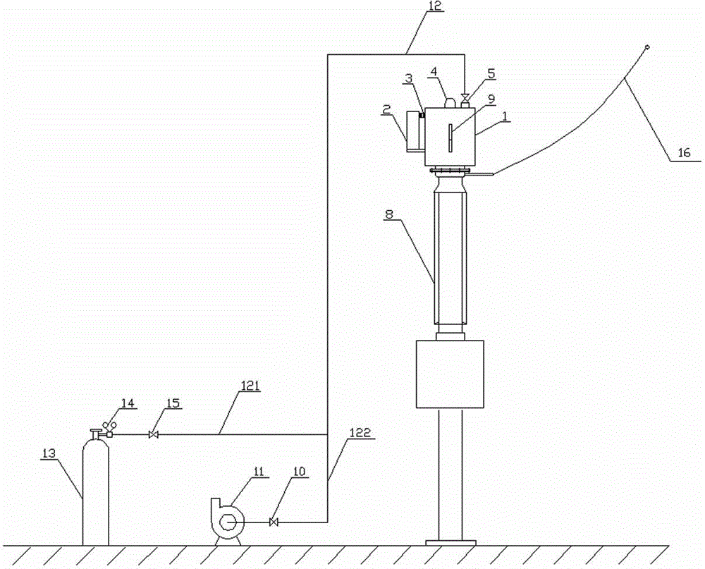
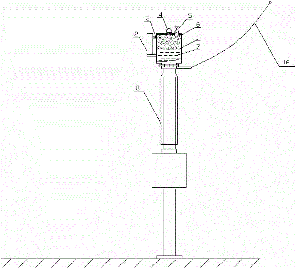
[0026] Please refer to figure 1 , the present invention provides a SF6 sealed tank protection device for an electric high-voltage oil-filled transformer, including an electric high-voltage oil-filled transformer 8, characterized in that: a sealed tank 1 is connected to the top of the electric high-voltage oil-filled transformer 8, and the There is an air supply tank 2 on the side of the sealed tank 1, a corrugated air supply valve 3 is arranged between the air supplement tank 2 and the sealed tank 1, a pressure relief valve 4 is arranged in the middle of the upper surface of the sealed tank 1, and the sealed tank 1 The upper surface of 1 is also provided with a vent valve 5, the vent valve 5 is connected to a main pipe 12, the main pipe 12 is connected to an SF6 gas cylinder 13 through a first branch pipe 121, and the main pipe 12 is connected to a vacu...


PUM


Abstract

The invention relates to an SF 6 sealing pot protective device for an electric high-pressure oil-filling mutual inductor. The SF 6 sealing pot protective device comprises the electric high-pressure oil-filling mutual inductor, the top of the electric high-pressure oil-filling mutual inductor is connected with a sealing pot, the side face of the sealing pot is provided with an air supplying pot, a ripple air supplying valve is arranged between the air supplying pot and the sealing pot, the middle of the upper surface of the sealing pot is provided with a pressure releasing valve, the upper surface of the sealing pot is provided with an air releasing valve, the air releasing valve is connected with a main pipe, the main pipe is connected with an SF 6 air bottle through a first branch pipe, the main pipe is connected with a vacuum pump through a second branch pipe, the first branch pipe is provided with an air adding valve, the joint of the first branch pipe and the SF 6 air bottle is provided with a pressure reducing valve, and the second branch pipe is provided with a vacuum valve. The contact between air and tidal air and an oil face inside the mutual inductor is separated, and the functions of fire proofing and fire fighting are achieved.

Description

technical field [0001] The invention relates to a protection device for an SF6 sealed tank of an electric high-voltage oil-filled transformer and a method for using it. Background technique [0002] At present, the sealing protection device of the traditional high-voltage oil-filled transformer for electric power is mainly the protection device of the metal corrugated expander or the gland is tightly sealed. To compensate the pressure change caused by the rise and fall of the oil level in the transformer due to the thermal expansion and contraction of the oil inside the transformer, but because the metal corrugated expander is made of stainless steel metal, due to the friction force during stretching and shrinking movements, Jamming phenomenon is easy to occur, resulting in poor rise and fall of the oil level of the transformer, and even a false oil level of the oil-filled transformer. Air contact is also susceptible to moisture. The power high-voltage oil-filled transform...

Claims


Application Information

Patent Timeline
Patent Type & Authority Applications(China)
IPC IPC(8): H01F38/20H01F27/00H01F27/14
Inventor 林晓铭
Owner STATE GRID CORP OF CHINA
Learn More