
Electromagnetic cutting knife implementing method based on time reversal transmission

A technology of time reversal and implementation method, which is applied in the direction of electrical digital data processing, special data processing applications, instruments, etc., can solve the problems of electromagnetic wave dynamic focusing that have not been reported, and achieve the effect of simple method

Inactive Publication Date: 2015-08-26
UNIV OF ELECTRONICS SCI & TECH OF CHINA
View PDF4 Cites 4 Cited by
  • Summary
  • Abstract
  • Description
  • Claims
  • Application Information

AI Technical Summary

Problems solved by technology

At present, most studies based on TR focus on the single-point focusing of electromagnetic waves and the instantaneous focusing of a certain field intensity distribution, and the research on the dynamic focusing of electromagnetic waves has not been reported yet.

Method used

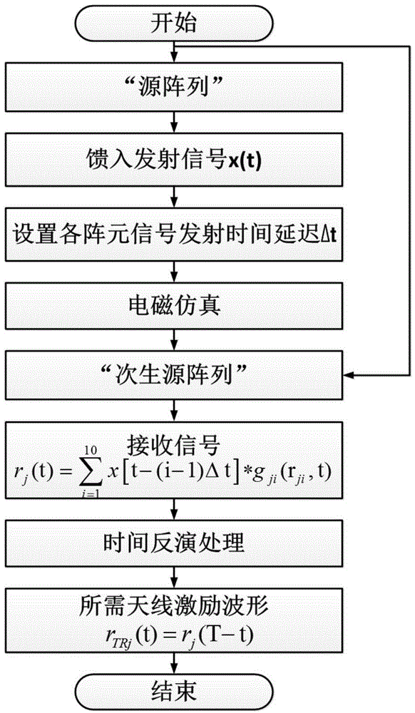

Image

  • Electromagnetic cutting knife implementing method based on time reversal transmission
  • Electromagnetic cutting knife implementing method based on time reversal transmission
  • Electromagnetic cutting knife implementing method based on time reversal transmission

Examples


Embodiment

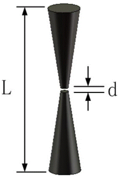
[0037] In the embodiment of the present invention, both the source array and the secondary source array use the same dipole antenna unit, such as image 3 As shown, this dipole antenna is composed of two metal conical columns with a total length L=41.3mm. The distance between the upper and lower conical columns is d=1mm. 4mm, the radius of the small circle is 1mm; the resonant frequency of the dipole antenna is 2.45GHz, and its return loss characteristics are as follows Figure 4 As shown, at 2.45GHz, its corresponding H-plane pattern is as follows Figure 5 shown. The excitation signal of the source array in the embodiment of the present invention is a modulated Gaussian pulse x(t) of 1.5-3.5 GHz, Image 6 is the specific waveform of x(t).

[0038] According to the above requirements, electromagnetic modeling and simulation are carried out in the electromagnetic simulation software, and the required antenna excitation waveform is synthesized, and the dynamic focusing of el...


PUM


Abstract

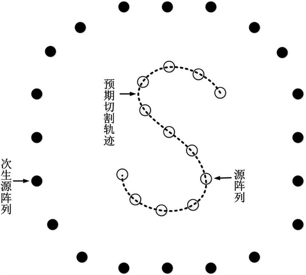
The present invention provides an electromagnetic cutting knife implementing method based on time reversal transmission and belongs to the field of spatial propagation and control of electromagnetic waves. The method comprises the steps that: based on a time-reversal electromagnetic theory and by virtue of a space-time synchronous focusing and transmission mechanism of TR (Time Reversal) electromagnetic waves, array elements, arranged on a source array on an expected cutting track, asynchronously transmit signals at a certain time interval, and signals received by secondary generation source arrays arranged around the source array are reversed on a time axis, so that time reversal waveforms are obtained; and finally, the source array is removed. the obtained time reversal wave forms are respectively fed into each array element of the corresponding secondary generation source arrays and are synchronously transmitted, i.e. motion of an electromagnetic wave focusing point along the predicted cutting track can be implemented and dynamic focusing of the electromagnetic waves is implemented. According to the method provided by the present invention, the focusing transmission mechanism of the time reversal is utilized and required excitation waveforms can be obtained accurately and efficiently by once forward transmission of a source array signal, so that dynamic focusing of the electromagnetic waves on the expected cutting tracking is implemented.

Description

technical field [0001] The invention belongs to the field of space propagation and control of electromagnetic waves, and in particular relates to a realization method of an "electromagnetic cutter" based on time inversion transmission. Background technique [0002] For a long time, the research on the spatial propagation and control of electromagnetic waves has mainly focused on the far-field area of ​​the antenna. Various shaped beams are generated by adjusting the amplitude or phase of the feed signal of the antenna array elements, such as the literature "A beam-switching antenna array with shaped radiation patterns (IEEE Antennas and Wireless Propagation Letters, 11:818-821, 2012, H.Wang, Z.J.Zhang, Z.H.Feng)" and the literature "Versatile beam forming with concentric excitations based on multiple weighted sinc or bessel function distribution (IEEE Trans. Antennas and Propagation, 61(8):4082-4090, Aug.2013, K.W.Xu, H.Li, Z.B.Zhu, et al)" etc. Beamforming has been widely ...

Claims


Application Information

Patent Timeline
Patent Type & Authority Applications(China)
IPC IPC(8): G06F17/50
Inventor 赵德双孙虎陈志新王秉中
Owner UNIV OF ELECTRONICS SCI & TECH OF CHINA
Learn More