
Aerial vehicle flight error correcting device and correcting method as well as unmanned aerial vehicle

A technology for an aircraft and a flight controller, applied in the field of aircraft, can solve problems such as inability to locate and fly normally, accuracy error, and aircraft navigation accuracy error, and achieve the effects of ensuring high-precision navigation, saving time and manpower, and high equipment stability

Active Publication Date: 2015-08-26
北京远度互联科技有限公司
View PDF6 Cites 9 Cited by
  • Summary
  • Abstract
  • Description
  • Claims
  • Application Information

AI Technical Summary

Problems solved by technology

[0004] However, in some enclosed spaces, spaces where GPS signals may be blocked, and areas with strong electromagnetic interference, GPS signals cannot be transmitted to the aircraft normally. When the aircraft cannot receive GPS signals, it can only rely on inertial navigation technology to fly. The inertial navigation technology is realized through the integral principle, and there must be a certain error in itself, and the error will gradually accumulate and increase with the prolongation of time, which will cause a large error in the long-term navigation accuracy of the aircraft, so that in a closed space Or in an environment where GPS signals cannot be received, such as areas with strong electromagnetic signal interference, the flight accuracy of the aircraft will be greatly deviated, and even normal positioning and flight will not be possible.
[0005] In addition, because relying solely on inertial navigation will cause large accuracy errors after a period of time, a long period of initial calibration is required after each flight and before the second flight, which is cumbersome and time-consuming.

Method used


Image

  • Aerial vehicle flight error correcting device and correcting method as well as unmanned aerial vehicle
  • Aerial vehicle flight error correcting device and correcting method as well as unmanned aerial vehicle
  • Aerial vehicle flight error correcting device and correcting method as well as unmanned aerial vehicle

Examples


Embodiment Construction

[0046] In order to make the purpose, technical solutions and advantages of the embodiments of the present invention more clear, specific embodiments will be described in detail below with reference to the accompanying drawings.

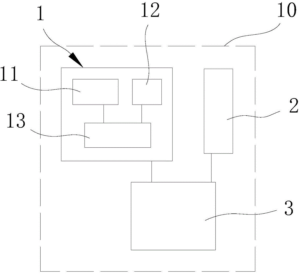
[0047] Please refer to figure 1 , is a schematic diagram of the aircraft flight error correction device module of the present invention, as shown in the figure, the aircraft flight error correction device of the present invention mainly includes: an optical flow sensing module 1, which is arranged on the aircraft 10, and the optical flow sensing module 1 can detect the height of the aircraft and continuous Take ground images, and perform data processing to obtain aircraft velocity signals and aircraft displacement signals; inertial navigation module 2 is arranged on the aircraft 10 for inertial navigation of the aircraft 10; flight controller 3 is arranged on the aircraft 10, connected to the The flow sensing module 1 and the inertial navigation modul...


PUM


Abstract

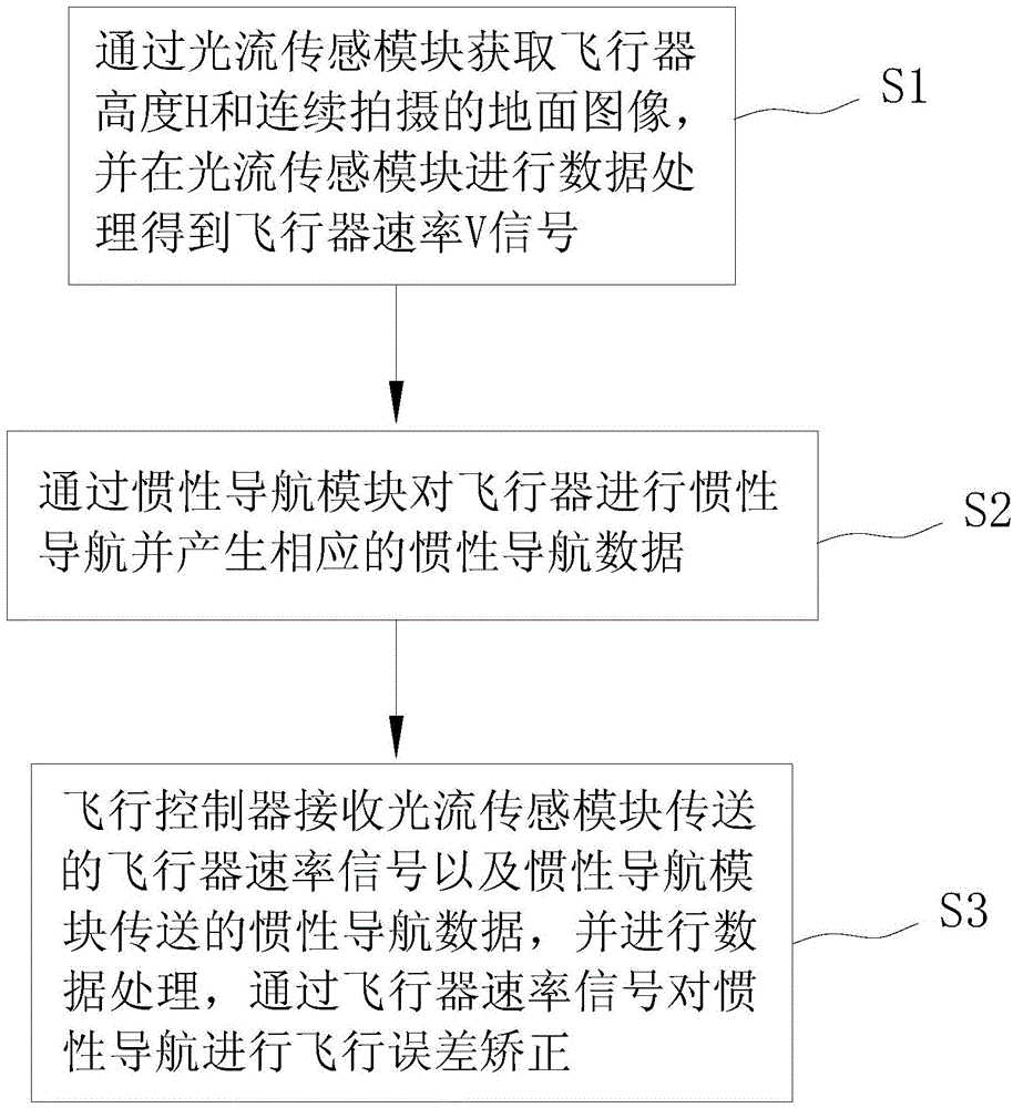
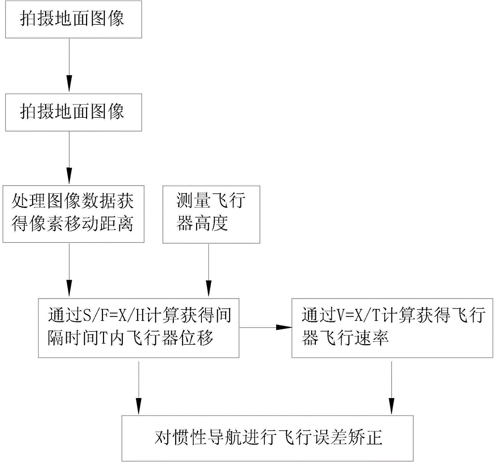
The invention discloses an aerial vehicle flight error connecting device and correcting method as well as an unmanned aerial vehicle. The correcting method comprises steps as follows: an aerial vehicle height H and continuously shot ground images are acquired by an optical flow sensing module, and the optical flow sensing module performs data processing to obtain signals of aerial vehicle velocity V; an inertial navigation module performs inertial navigation on the aerial vehicle and generates corresponding inertial navigation data; a flight control unit receives the aerial vehicle velocity signals transmitted by the optical flow sensing module and the inertial navigation data transmitted by the inertial navigation module and performs data processing, and flight error correction is performed on the inertial navigation by the aid of the aerial vehicle velocity signals. According to the technical scheme, flight errors can be still corrected in the environment where GPS (global positioning system) signals cannot be received and accurate navigation for the aerial vehicle is realized.

Description

technical field [0001] The invention relates to the technical field of aircraft, in particular to an aircraft flight error correction device, a correction method and an unmanned aerial vehicle. Background technique [0002] With the development of science and technology, UAV flying equipment began to enter people's field of vision, and gradually penetrated into people's lives, improving people's lives. The application range of unmanned aerial vehicle is more and more extensive, for example, it has a wide range of applications in professional fields such as aerial photography, surveying, disaster control and real-time monitoring. [0003] At the same time, higher requirements are put forward for the navigation and positioning accuracy of the aircraft. At present, the commonly used navigation technologies during the flight of the aircraft mainly include inertial navigation and satellite positioning (GPS) navigation. Accurate navigation and positioning. [0004] However, in s...

Claims


Application Information

Patent Timeline
IPC IPC(8): G01C21/16
CPCG01C21/165
Inventor 杨霖齐向阳杨建军
Owner 北京远度互联科技有限公司
Learn More