
Electric car charging device capable of being placed beneath ground

A charging device and electric vehicle technology, applied in electric vehicle charging technology, electric vehicles, battery circuit devices, etc., can solve the problems of crowding golden ground, incompatible urban environment, occupation, etc., to avoid electric shock accidents, improve land utilization, good safety effect

Active Publication Date: 2015-08-26
青岛艾迪森科技股份有限公司
View PDF7 Cites 7 Cited by
  • Summary
  • Abstract
  • Description
  • Claims
  • Application Information

AI Technical Summary

Problems solved by technology

[0002] The existing electric vehicle charging devices and charging stations are mostly installed in buildings on the ground, occupying the land use area on the ground, and the supporting facilities in squares and downtown are mostly installed in the form of box rooms, occupying the golden ground, which is incompatible with the surrounding beautiful urban environment, so A new charging method is urgently needed to solve this problem

Method used


Image

  • Electric car charging device capable of being placed beneath ground

Examples


Embodiment 1

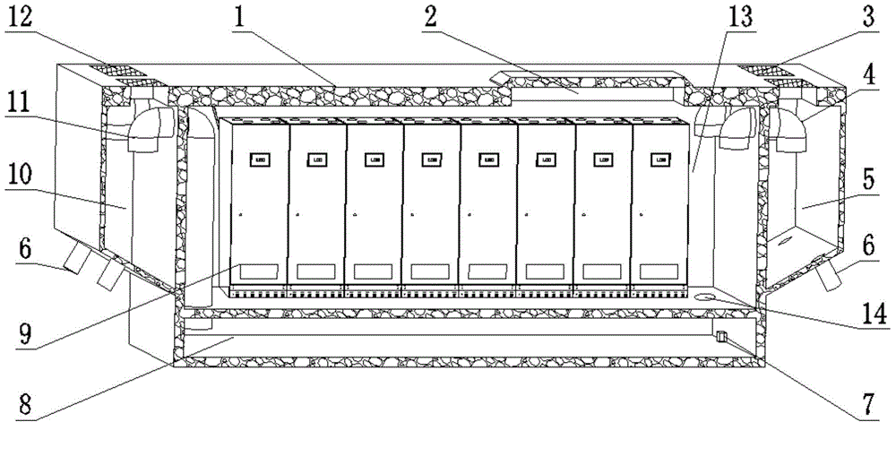
[0028] Such as figure 1 As shown, the electric vehicle charging device that can be placed underground according to the present invention includes a charging box 9 and a concrete structure 1 located below the ground surface. The charging box 9 is located in the concrete structure 1; the concrete structure 1 includes a rectangular parallelepiped storage bin 13 , Rectangular parallelepiped-shaped air inlet and water-proof bin 8, right-angled trapezoid-shaped inlet and drainage bin 10 with a sloped bottom, and right-angled trapezoid-shaped exhaust and drain bin 5 with a sloped bottom. The charging box 9 is located in the placement bin 13, and The wind and water-proof warehouse 8 is located directly below the resettlement chamber 13, and the air intake and drainage chambers 10 and the resettlement chamber 13 are located on both sides of the charging box 9; , There is an air outlet 3 above the exhaust air and drainage bin 5; the concrete structure 1 also includes an air inlet pipe 11...

Embodiment 2

[0034] In this embodiment, the difference between the electric vehicle charging device that can be placed underground and the first embodiment is that the inlet duct 11 is arranged in the inlet and drainage bin 10 with the duct mouth facing downward, and the exhaust duct 4 The pipe openings in the exhaust air and drainage bin 5 and the installation bin 13 are all set downward. In this way, it is possible to ensure that the airflow is passed through, and at the same time it has the effect of waterproofing.

[0035] Others are the same as in Example 1.

Embodiment 3

[0037] The difference between this embodiment and the first embodiment is that, under the premise of ensuring the charging effect of the present invention, the power lead out from the charging box 9 is divided into multiple branches, which are connected to multiple charging points on the ground. For multiple cars.

[0038] Others are the same as in Example 1.


PUM


Abstract

The invention relates to an electric car charging device capable of being placed beneath ground, belongs to the field of charging of electric cars, and solves the main problem that the conventional electric car charging device occupies environmental spaces and reduces the land utilization rate. The electric car charging device comprises a charging case, and a concrete structure positioned beneath the ground surface, wherein the charging case is positioned in the concrete structure; the concrete structure comprises a cuboid accommodating bin, a cuboid air inlet water-proof bin, a right-trapezoid-shaped air inlet water drainage bin of which the bottom is an inclined plane and a right-trapezoid-shaped air exhaust water drainage bin of which the bottom is an inclined plane; the charging box is positioned in the accommodating bin; the air inlet water-proof bin is positioned under the accommodating bin; the air inlet water drainage bin and the air exhaust water drainage bin are positioned on the two sides of the accommodating bin. The electric car charging device is mainly used for charging electric cars.

Description

Technical field [0001] The invention relates to an electric vehicle charging device that can be placed underground, and belongs to the field of electric vehicle charging. Background technique [0002] Existing electric vehicle charging devices, charging stations are mostly installed in above-ground buildings, occupying the land use area on the ground, squares and downtowns are mostly installed in the form of box houses, squeezing the golden ground, and incompatible with the surrounding beautiful urban environment, so A new charging method is urgently needed to solve this problem. Summary of the invention [0003] The purpose of the present invention is to overcome the above-mentioned shortcomings in the prior art, and propose an electric vehicle charging device that can be placed underground, which improves the land utilization rate without affecting the surrounding environment, has theft prevention, electric shock prevention, and is convenient to use and maintain And other effec...

Claims


Application Information

Patent Timeline
Patent Type & Authority Applications(China)
IPC IPC(8): E02D29/045H02J7/00
CPCB60L53/31Y02T10/70Y02T10/7072Y02T90/12
Inventor 王照忠郝德成
Owner 青岛艾迪森科技股份有限公司
Learn More