
Method for correcting oil reservoir top surface micro structure by using information of horizontal well stratum penetrating point

A technology for information correction and horizontal wells, which is applied in seismology and seismic signal processing for well logging records. It can solve the problems of difficult to accurately characterize the excessive shape of microstructures between wells, lack of formation dip and dip control, and difficult to carry out.

Active Publication Date: 2015-08-19
SHANDONG UNIV OF SCI & TECH
View PDF2 Cites 13 Cited by
  • Summary
  • Abstract
  • Description
  • Claims
  • Application Information

AI Technical Summary

Problems solved by technology

Both of the above two traditional research methods have certain limitations. The first method only uses well point elevation data for correction, lacks the control of formation dip and dip, and it is difficult to accurately characterize the transitional shape of microstructures between wells; the second method The limitation lies in the accuracy of the original seismic data. If the accuracy of seismic data cannot meet the requirements of microstructure research, this work will be difficult to carry out.

Method used


Image

  • Method for correcting oil reservoir top surface micro structure by using information of horizontal well stratum penetrating point
  • Method for correcting oil reservoir top surface micro structure by using information of horizontal well stratum penetrating point
  • Method for correcting oil reservoir top surface micro structure by using information of horizontal well stratum penetrating point

Examples


Embodiment Construction

[0039] The method for correcting the microstructure of the top surface of the reservoir by using the information of the entry point of the horizontal well according to the present invention will be described in detail below with reference to the accompanying drawings.

[0040] Case 1: When a horizontal well penetrates along the formation dip

[0041] 1. Calculate the true dip angle α of the formation t

[0042] (1) Calculate the formation apparent dip angle α a

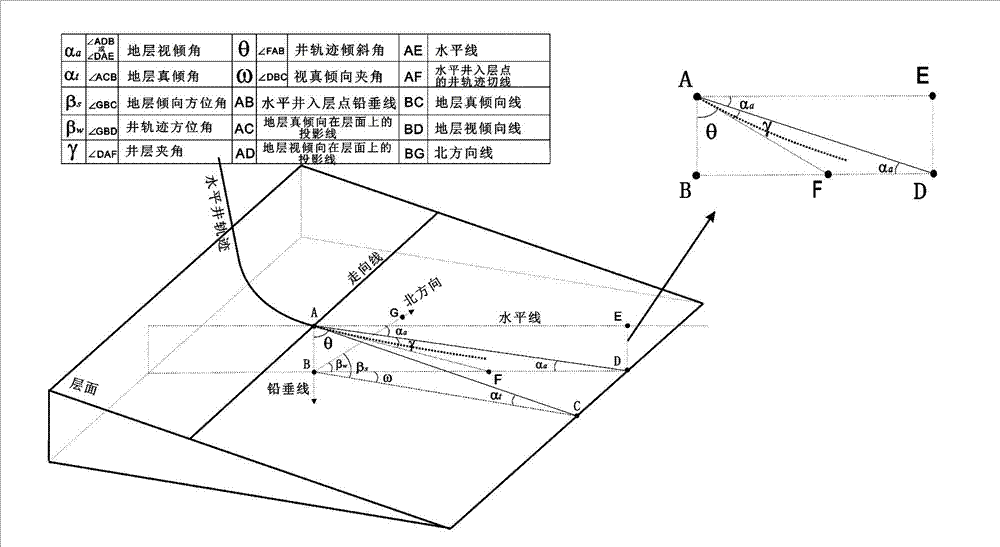
[0043] First, according to the delay response characteristics of the natural gamma ray curve when it passes through the sand-shale interface, the delay distance is directly read on the comprehensive logging map, and half of it is recorded as L; then, the detection depth of the horizontal well natural gamma ray logging curve is established Statistical graph (or use the average detection depth), get the detection depth r of the gamma logging tool; then, by the attached Figure 4 As shown in the triangular relationsh...


PUM


Abstract

The invention relates to a technology for calculating a horizontal well oil reservoir development stratum true dip angle so as to correct an oil reservoir top surface micro structure, and particularly relates to a method for correcting the oil reservoir top surface micro structure by using information of a horizontal well stratum penetrating point. The method comprises the steps of determining the length of a delay interval by using delayed response characteristics of a natural gamma-ray logging curve when penetrating through a sand shale boundary, deducing and calculating a more accurate calculation method for a stratum true dip angle of the horizontal well stratum penetrating point by being combined with a well drilling inclination angle and an azimuth angle explained in the logging process, drawing a stratum dip angle plane graph, correcting the horizontal well oil reservoir top surface micro structure by taking the stratum dip angle plane graph as a basis, drawing a contour map with the spacing being less than 2m, and guiding reasonable development of an oil reservoir and potential tapping of residual oil. The method provided by the invention overcomes limitations in carrying out correction on the top surface micro structure by only using well point altitude and seismic data at present, provides a method for correcting horizontal well oil reservoir development top surface micro structure, makes full use of the information of the horizontal well stratum penetrating point, and acquires the true stratum dip angle, thereby studying the oil reservoir top surface micro structure more accurately.

Description

technical field [0001] The invention relates to a method for calculating the true dip angle of a reservoir for horizontal well development and correcting the microstructure of the top surface of the reservoir by using the true dip angle distribution map. Background technique [0002] Microstructure refers to the structural features shown by the fine fluctuations of the oil layer itself on the general reservoir structural background, with low uplifts and depressions, small closed areas, no certain directionality, irregular shapes, and irregular distribution. Therefore, it is difficult to find the local microstructure without more detailed research. The practice of oilfield development shows that the shape and amplitude of the microstructure directly affect the waterflooding development of the reservoir and the distribution of remaining oil, which is of great significance to the rational development of the reservoir and the tapping of the remaining oil potential in the later s...

Claims


Application Information

Patent Timeline
IPC IPC(8): G01V1/40G01V1/36
Inventor 王金凯卢浩谢俊
Owner SHANDONG UNIV OF SCI & TECH
Learn More