
Method for estimating differential mode interference noise impedance of equipment

A technology of differential mode interference and differential mode noise, which is applied in the field of estimation of differential mode interference noise impedance of equipment, and can solve problems such as difficult acquisition of differential mode noise source impedance and unobtainable differential mode noise source impedance

Inactive Publication Date: 2015-08-19
NORTHEAST AGRICULTURAL UNIVERSITY
View PDF4 Cites 1 Cited by
  • Summary
  • Abstract
  • Description
  • Claims
  • Application Information

AI Technical Summary

Problems solved by technology

[0007] The invention is used to solve the problem that the source impedance of the differential mode noise is difficult to obtain, and is mainly used to provide the amplitude range of the source impedance of the differential mode noise in the noise
In view of the above two problems, in practical problems, the source impedance of differential mode noise generally cannot be obtained

Method used

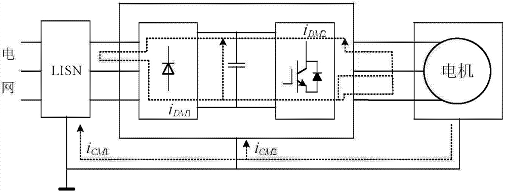
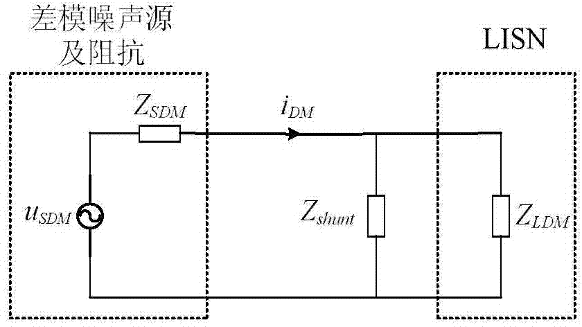

Image

  • Method for estimating differential mode interference noise impedance of equipment
  • Method for estimating differential mode interference noise impedance of equipment
  • Method for estimating differential mode interference noise impedance of equipment

Examples


Embodiment Construction

[0024] Z in series with 1Ω resistor and 0.1µF capacitor shunt The present invention will be described in detail by taking a parallel impedance device as an example.

[0025] pair impedance Z shunt In the capacitor part, the relationship between the impedance amplitude and the frequency has been measured by an impedance analyzer, such as Figure 4 shown.

[0026] Measure the voltage U before and after the access capacitor LDM0 with U LDM the magnitude of . u LDM0 with U LDM The relationship between the amplitude and the frequency variation is shown in Figure 5 and Figure 6 .

[0027] According to the measured value, follow the third step to get the insertion loss IL DM , see Figure 7 .

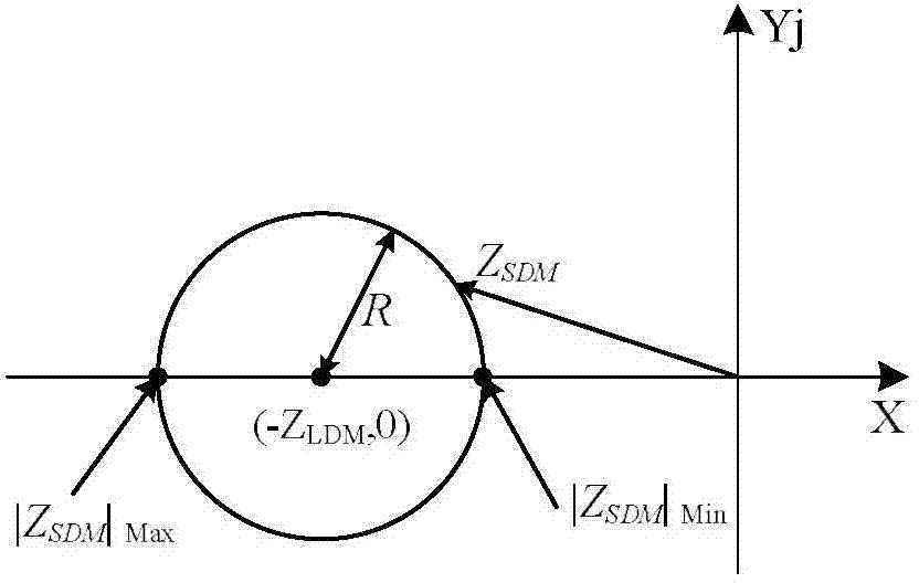
[0028] According to step 4-step 7, the noise source impedance range is obtained by drawing, and then the range of each frequency band is combined to obtain the estimated range of the entire frequency domain.

[0029] The actual measured value of the differential mode noise sourc...


PUM


Abstract

The invention discloses a method for measuring and estimating differential mode interference noise impedance through insertion loss. According to the method, a known impedance amplitude element is inserted into a circuit to measure voltage before and after the element is inserted so as to obtain the insertion loss value of the element. A noise source impedance amplitude range is obtained by drawing an impedance plane graph. According to the method, the operation is simple and easy, the experimental condition is simple, and the result precision is relatively high. The impedance value estimated by the estimation method is compared with a measured value of a laboratory, and the compared result indicates that the estimation range precision is high. Moreover, the estimation method also can be suitable for a system with unknown impedance, the impedance value estimated by the method is beneficial to later-stage filter parameter design, and the results also can provide effective data for an electromagnetic interference protective problem.

Description

(1) Technical field [0001] The present invention relates to a method for estimating differential-mode internal impedance in various motor drive systems. Since the design of the filter needs to know the size of the noise source impedance, it provides a basis for selecting a suitable filter topology for the power converter, and belongs to power electronics electromagnetic interference The field of inhibition and design. (2) Background technology [0002] Differential mode interference is a common and influential interference in electronic and electrical equipment. Compared with common-mode interference, another type of interference in the equipment, differential-mode interference is more difficult to remove and has an impact on the load. At present, the more common method to suppress differential mode interference is to add a passive filter, and the premise of selecting a suitable filter is to be able to obtain the differential mode source impedance of the noise source. [0...

Claims


Application Information

Patent Timeline
IPC IPC(8): G01R27/04G01R29/26
Inventor 赵峻颖宋文良孙亚秀
Owner NORTHEAST AGRICULTURAL UNIVERSITY
Learn More