
Pin hole apparatus and pin hole adjusting method

A pinhole and loading stage technology, applied in the field of confocal microscopy scanning systems, can solve the problems of inability to accurately feedback pinhole size, no adjustment degree selection, and constrain the imaging capability of the confocal system, and achieve easy and precise positioning and control. Enhanced optical confocal capability and continuously adjustable pinhole size

Inactive Publication Date: 2015-08-19
SHANGHAI ADVANCED RES INST CHINESE ACADEMY OF SCI
View PDF4 Cites 3 Cited by
  • Summary
  • Abstract
  • Description
  • Claims
  • Application Information

AI Technical Summary

Problems solved by technology

If the pinhole cannot effectively match the center of the beam, it will cause the loss of effective signal light and the infiltration of stray light
[0006] Existing pinhole devices have their own shortcomings: for example, the electric pinhole wheel of Thorlabs has 16 pinholes of different sizes built in the pinhole device, and only one of the pinholes closest to the user's needs can be selected for use. hole, there is no adjustment degree option, and a more accurate pinhole size cannot be selected
Another example is Jobin Yvon’s manual pinhole wheel. Although its manual adjustment system can adjust the size of the pinhole, it cannot accurately feedback the adjusted pinhole size, resulting in the inability to capture accurate pinhole parameter information.
These deficiencies prevent the existing pinhole design scheme from providing a more precise pinhole size, which in turn restricts the imaging capability of the confocal system to a certain extent

Method used


Image

  • Pin hole apparatus and pin hole adjusting method
  • Pin hole apparatus and pin hole adjusting method
  • Pin hole apparatus and pin hole adjusting method

Examples


Embodiment Construction

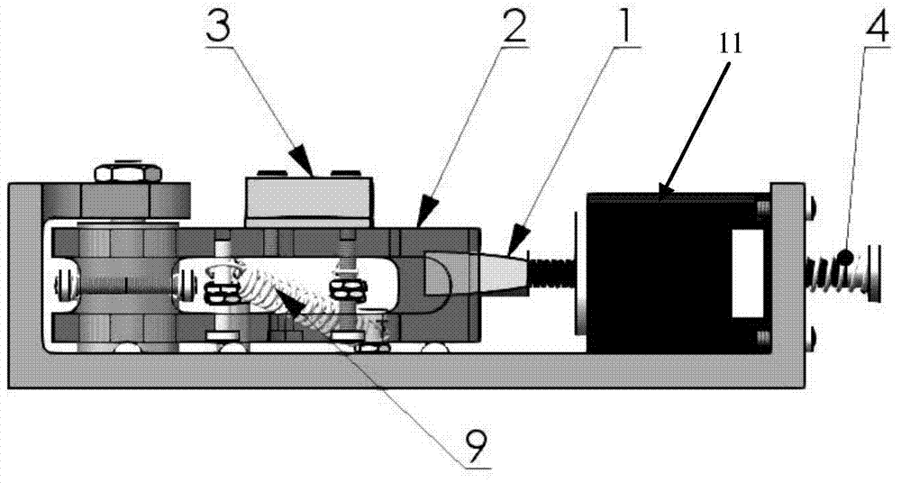
[0039] Such as figure 2 Said is a longitudinal sectional structural view of the pinhole device of the embodiment of the present invention; image 3 Said is a top view of the pinhole device of the embodiment of the present invention; Figure 4 Said is the right side view of the pinhole device of the embodiment of the present invention; Figure 5 Said is a three-dimensional view of the pinhole device of the embodiment of the present invention; Figure 6A Said is a schematic diagram of the sheet 12 of the pinhole device of the embodiment of the present invention; Figure 6B The above is a schematic diagram of the pinhole 14 of the pinhole device in the embodiment of the present invention.

[0040] The pinhole device in the embodiment of the present invention includes: a stepping motor 11, two movable sliding blocks 2, two sheet loading tables 3, and two sheets 12.

[0041] The front end of the screw of the stepping motor 11 is provided with a pin-shaped nut 1, and the stepping motor 1...


PUM


Abstract

The invention discloses a pin hole apparatus. The pin hole apparatus comprises a stepping motor, two movable sliding blocks, two slice loading stages and two slices; and the front end of the screw of the stepping motor is provided with a pin-shaped nut, the slices are arranged on the slice loading stages respectively, and the slice loading stages are arranged on the movable sliding blocks respectively. The two slices are respectively provided with a hole, holes of the two slices are superposed up and down to form a pin hole, and the size of the pin hole is determined by the superposed area of the holes of the two slices; and the stepping motor controls the pin-shaped nut to move linearly in order to rotate the two movable sliding blocks, and the size of the pin hole can be adjusted through the rotation of the movable sliding blocks. The invention also discloses a pin hole adjusting method. The pin hole apparatus can realize electrically controlled continuous adjustment of the size of the pin hole, has a precise and accurate position electron feedback ability, can acquire accurate pin hole dimension parameters, and makes a confocal system have strong imaging ability.

Description

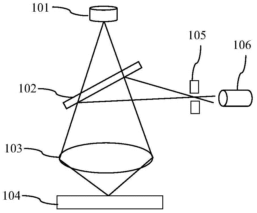
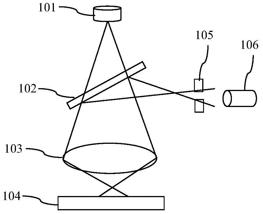
Technical field [0001] The invention relates to a confocal microscopy scanning system, in particular to a pinhole device; the invention also relates to a pinhole adjustment method. Background technique [0002] Confocal systems are widely used in the field of optical microscopy. Among them, Laser Scanning Confocal Microscope (LSCM) is an experimental instrument widely used in the field of biomedicine. It has high-speed imaging, high spatial resolution, and is non-invasive The advantages of non-destructive continuous optical tomography and three-dimensional scanning have become powerful research tools in many fields such as morphology, molecular cell biology, and materials science. [0003] Such as Figure 1A Shown is the first schematic diagram of the existing laser scanning confocal microscope, which corresponds to the focusing situation; Figure 1B Shown is a schematic diagram of an existing laser scanning confocal microscope Figure II , The sign Figure II Corresponds to the def...

Claims


Application Information

Patent Timeline
Patent Type & Authority Applications(China)
IPC IPC(8): G01N21/01G01N21/64G01Q60/48G01Q60/46
Inventor 王中阳沈灏刘书朋
Owner SHANGHAI ADVANCED RES INST CHINESE ACADEMY OF SCI
Learn More