Rectangular open magnetic field type low-frequency vibration calibration table with double-magnetic-circuit two-end symmetric excitation

A low-frequency vibration, calibration table technology, applied in measuring devices, instruments, measuring ultrasonic/sonic/infrasonic waves, etc., can solve the problems of difficult to guarantee assembly accuracy, magnetic circuit influence, poor compensation effect, etc., to ensure processing and assembly accuracy. , The effect of high air gap magnetic induction intensity, convenient processing and assembly

Active Publication Date: 2015-08-19
HARBIN INST OF TECH
View PDF10 Cites 3 Cited by
  • Summary
  • Abstract
  • Description
  • Claims
  • Application Information

AI Technical Summary

Problems solved by technology

[0005] The disadvantages of the above two technical solutions are: 1) the cylindrical outer yoke needs to be processed in the long inner dimension, which is difficult to process and difficult to guarantee the accuracy; 2) when the cylindrical permanent magnet is used, the through hole needs to be processed on the permanent magnet And it is fixed on the yoke by non-magnetic bolts, the assembly is complicated and will affect the magnetic circuit; when a cylindrical permanent magnet is used, it is difficult to sinter, process, magnetize and assemble a large-sized cylindrical permanent magnet; 3) The cylindrical outer yoke needs to be set on the central yoke. If the permanent magnet is magnetized first and then assembled, the assembly is very difficult and the assembly accuracy is difficult to guarantee; if the permanent magnet made of AlNiCo material is used, it can be assembled first and then assembled. Magnetization method, but due to the low coercivity of AlNiCo material permanent magnets, the performance is not good, which seriously restricts the mechanical properties and indicators
[0007] The shortcomings of this technical solution are: 1) The electromagnetic drive structure is composed of multiple structural combinations and splicing, and the structure is complex; the small permanent magnet needs to be installed on the wedge-shaped pole piece by glue or other methods, which is complicated to assemble and difficult to ensure. Accuracy; 2) The static magnetic induction intensity at a certain position in the air gap is directly related to the working point of the permanent magnet at that place, and the uniformity of the magnetic field in the entire air gap is difficult to guarantee, and the requirements for the consistency of the materials and processes of the small permanent magnets are relatively high. High; 3) The permanent magnet directly faces the air gap, and the additional magnetic field generated after the working coil is energized will have a forced magnetization or demagnetization effect on it. When a large current is passed through the working coil, it is easy to cause irreversible demagnetization of the permanent magnet ;4) When the working coil is energized, the magnetic flux on one side of the coil increases and the magnetic flux on the other side decreases. Since the permanent magnet directly faces the air gap, the magnetic circuit on the side where the magnetic flux increases is easy to saturate. The increased magnetic flux is less than the decreased magnetic flux on the other side, resulting in a decrease in the average magnetic induction at the location of the coil, which in turn distorts the waveform of the generated standard vibration signal
[0009] (1) It is difficult to ensure the uniformity of the magnetic induction intensity distribution of the main magnetic circuit in the long air gap
Before the coil is energized, the permanent magnet is excited to form a stable distribution of the magnetic induction intensity of the main magnetic circuit. As the stroke of the vibration calibration table increases, it is difficult to ensure the uniformity of the magnetic field in the long air gap, which directly affects the linearity of the output electromagnetic driving force after the coil is energized. Some researchers try to compensate by adjusting the current waveform, but the effect is difficult to guarantee, especially for the compensation of high-order magnetic field non-uniformity errors. At present, no effective and highly practical compensation method has been proposed at home and abroad.
[0010] (2) The armature reaction after the working coil is energized restricts the linearity of the output electromagnetic driving force and the distortion of the output vibration waveform index
[0011] (3) It is difficult to process and assemble long yokes and large-size permanent magnets, and the accuracy is difficult to guarantee
On the one hand, eddy current loss will generate heat loss with a power of up to several hundred watts, and the heat generation is astonishing, which will bring a series of thermal disturbance and thermal deformation problems; on the other hand, the transient field problems caused by alternating magnetic fields and eddy currents, The actual performance index will have a large deviation from the results obtained by traditional design theory and analysis methods, which will seriously affect the design accuracy and effect.
[0013] In summary, restricted by the above problems, it is difficult to make further breakthroughs in the waveform distortion and other indicators of the standard low-frequency vibration generated by the existing technical solutions, and it is difficult to meet the high-precision calibration of low-frequency / ultra-low-frequency vibration, especially the next generation with very low frequency and The Need for Vibration Calibration of Ultra-Precise Features

Method used


Image

  • Rectangular open magnetic field type low-frequency vibration calibration table with double-magnetic-circuit two-end symmetric excitation
  • Rectangular open magnetic field type low-frequency vibration calibration table with double-magnetic-circuit two-end symmetric excitation
  • Rectangular open magnetic field type low-frequency vibration calibration table with double-magnetic-circuit two-end symmetric excitation

Examples


Embodiment Construction

[0040] The specific implementation manner of the present invention will be described in detail below with reference to the accompanying drawings, and examples will be given.

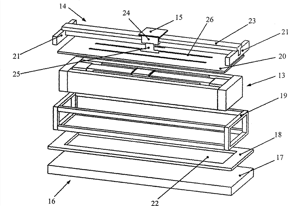
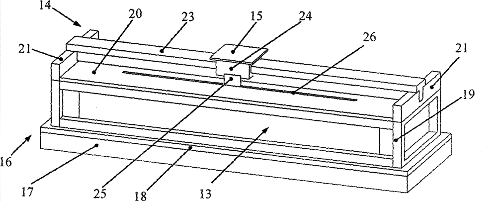
[0041] A rectangular open magnetic field type low-frequency vibration calibration table with symmetrical excitation at both ends of a double magnetic circuit, consisting of a base 16, an electromagnetic drive structure 13, a static pressure air flotation guide rail 14 and a workbench 15, the electromagnetic drive structure 13 and the static pressure air flotation The guide rail 14 is installed on the base 16 in an axis-parallel manner, and the workbench 15 is installed on the upper surface of the sliding sleeve 24 in the static pressure air bearing guide rail 14. The base 16 is composed of a bottom plate 17, a lower transition plate 18, a frame 19, The upper cover plate 20 and the rail support member 21 are stacked and installed from bottom to top. The electromagnetic drive structure 13 is installed on th...


PUM


Abstract

The invention provides a rectangular open magnetic field type low-frequency vibration calibration table with double-magnetic-circuit two-end symmetric excitation, belonging to the field of vibration measurement technology. A rectangular open magnetic field type magnetic circuit structure is provided. Two permanent magnets are symmetrically installed at two ends of a center magnet yoke and face magnetic poles. Two symmetric closed magnetic circuits are formed by magnet yokes. The strong magnetic field distribution with high uniformity is generated in air gaps. After a working coil is energized, the working coil is affected by Lorentz force in a magnetic field, and precisely controllable electromagnetic drive force is generated. The surfaces of the magnet yokes adjacent to the air gaps are provided with an array type micro structure in the form of deep trenches, and the eddy current loss can be effectively inhibited. The organic integration design of air lubricated guide technology is employed, and outstanding electromagnetic drive mechanical performance and high movement guide precision are obtained at the same time. According to the rectangular open magnetic field type low-frequency vibration calibration table, large stroke, high thrust, a linear electromagnetic driving force characteristic and high movement guide precision can be considered, and the high performance low frequency vibration calibration table is provided for low-frequency / ultra-low frequency vibration calibration.

Description

technical field [0001] The invention belongs to the technical field of vibration measurement, and mainly relates to a rectangular open magnetic field type low-frequency vibration calibration platform with symmetrical excitation at both ends of a double magnetic circuit. Background technique [0002] In the field of vibration measurement technology, the vibration calibration table that generates standard vibration signals is the core equipment to achieve high-precision vibration calibration, and it is also an important equipment that constitutes the national vibration measurement technology system. The high-precision vibration calibration table generally adopts the form of electromagnetic vibration table. In recent years, aerospace, building bridges, earthquake prevention and disaster reduction and other fields have raised the need for low-frequency / ultra-low-frequency vibration calibration. In order to improve the signal-to-noise ratio of the standard vibration signal and e...

Claims


Application Information

Patent Timeline
IPC IPC(8): G01H17/00
Inventor 崔俊宁谭久彬
Owner HARBIN INST OF TECH
Why Eureka
Try Eureka