
Automotive solar constant temperature system

A constant temperature system and solar energy technology, which is applied to vehicle parts, heating/cooling equipment, air handling equipment, etc., can solve the problems of excessive starting voltage of electric compressors, poor cooling effect, insufficient cooling in summer, etc., and achieve improved heat dissipation Effect, improvement of cooling efficiency, and effect of improving use efficiency

Active Publication Date: 2015-08-19
HUNAN UNIV AISHENG AUTO TECH DEV
View PDF6 Cites 5 Cited by
  • Summary
  • Abstract
  • Description
  • Claims
  • Application Information

AI Technical Summary

Problems solved by technology

Patent 2012100136015 is a solar-assisted automotive air-conditioning system, which uses a battery to drive the compressor for cooling, but there is a problem that the starting voltage of the electric compressor is too high; patent 201120389392.7 is an intelligent cooling system based on solar energy. The refrigeration principle of the semiconductor refrigeration sheet that can be cooled with low power, but does not describe the detailed method of implementing semiconductor refrigeration on the car; patent 200920177883.8 is a constant temperature control system for the car, which innovatively talks about the way of using semiconductor refrigeration sheets to use water cooling to dissipate heat Refrigeration in the car, but no mention of how to implement it in the car
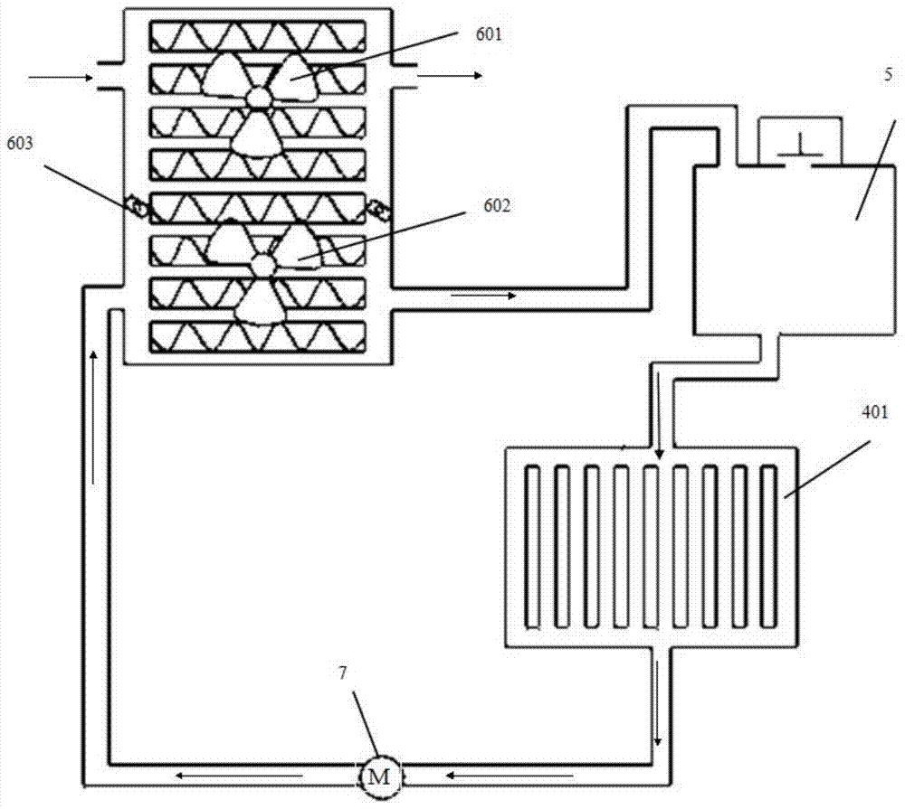
[0004] In addition, the traditional semiconductor air-conditioning system adopts the cooling method in the form of centrifugal fan, which has the disadvantage of poor cooling effect caused by insufficient cooling in summer

Method used


Image

  • Automotive solar constant temperature system
  • Automotive solar constant temperature system
  • Automotive solar constant temperature system

Examples


Embodiment Construction

[0018] The technical solution of the present invention will be described in detail below in conjunction with the accompanying drawings.

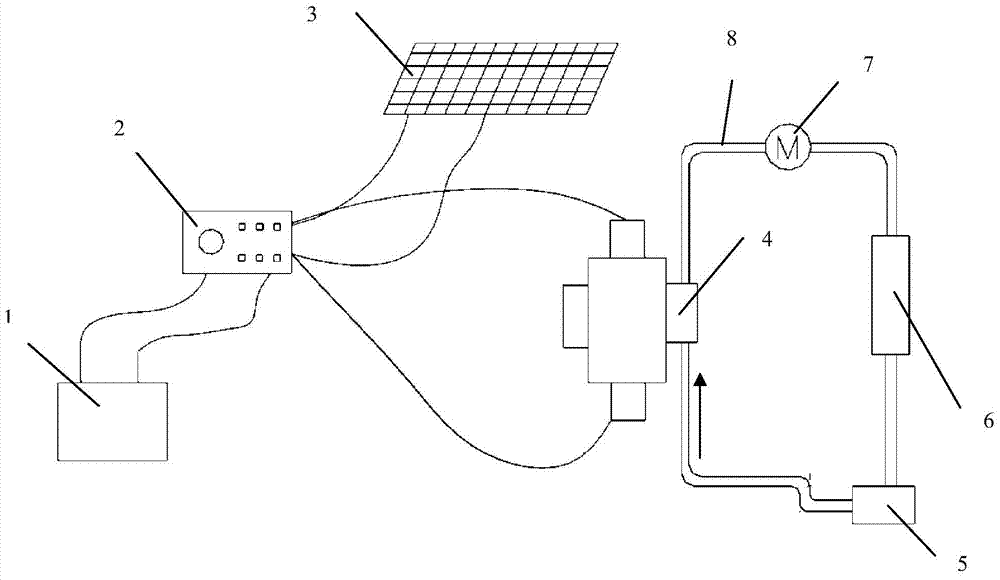
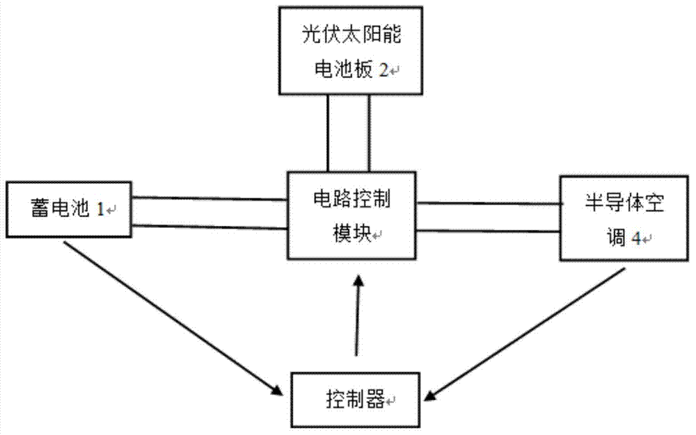
[0019] Such as figure 1 As shown, the solar constant temperature system of the present invention mainly includes a battery 1, a control system 2, a photovoltaic solar panel 3, a semiconductor air conditioner 4, a water tank 5, a condenser 6, a water-cooled driving pump 7, and a water pipe 8. Such as figure 1 As shown, the leads of the positive and negative poles of the battery 1 are respectively connected to the control system 2; wherein, the battery 1 is equipped with a power sensor, and according to the power signal of the battery 1, the control system 2 controls the output current of the battery 1 or controls the current received by the battery 1 for storage.

[0020] The outgoing wiring of the photovoltaic solar panel 3 is connected to the control system 2, wherein the control system can control the current of the photovoltaic solar pa...


PUM


Abstract

The invention relates to a solar constant temperature system. The solar constant temperature system comprises a storage battery (1), a control system (2), a photovoltatic solar panel (3), a semiconductor air conditioner (4), a water tank (5), a condenser (6) and a water cooling driving pump (7) and is characterized in that positive and negative outgoing wirings of the storage battery (1) are connected to the control system (2); an electric quantity sensor is arranged inside the storage battery (1); the control system (2) controls the storage battery (1) to output currents or controls the storage battery (1) to receive currents to be stored according to electric quantity signals of the storage battery (1). The solar constant temperature system enables an air conditioning system in the automobile to be intelligentialized and relieves the severe environment inside a passenger cabin when the automobile starts in hot summer; fully utilizes the solar energy and the storage battery on the automobile to coordinately supply energy for the constant temperature system; improves the heat dissipation effect of the semiconductor air conductor and improves the refrigerating efficiency of the semiconductor; improves a traditional radiator, utilizes the radiator in a time division mode and improves the utilization rate.

Description

technical field [0001] The invention relates to a medium and small power air conditioner, in particular to a solar energy constant temperature system for an automobile, belonging to the technical fields of vehicle design and air conditioner design. Background technique [0002] In today's world, low-carbon, energy-saving, and environmental protection have always been the constant themes of environmental protection around the world. [0003] In the hot summer, the harsh environment in the cabin of the crew after the car is parked outside for a period of time often makes the driver stop. The traditional solution is to open the window to ventilate and exchange heat after getting on the car, and then start the engine to run the car air conditioner to cool down. In this process, the driver must continue to endure the harsh environment in the car for a period of time. Therefore, in order to solve this problem, there is an idea about solar air conditioners for cars. Patent 201210...

Claims


Application Information

Patent Timeline
Patent Type & Authority Applications(China)
IPC IPC(8): B60H1/00
CPCY02T10/88B60H1/00478
Inventor 黄金凤罗庚汲彦军
Owner HUNAN UNIV AISHENG AUTO TECH DEV
Learn More