A flipping mechanism for a side-drawing mold

A technology of overturning mechanism and mould, which is applied in the direction of manufacturing tools, equipment for transporting casting molds, metal processing equipment, etc. It can solve problems such as overturning, mold collapse, and loud noise, so as to reduce the use of power components, reduce complexity and The effect of enlarged wiring and operating space

Active Publication Date: 2017-04-12
SUZHOU MINGZHI TECH
View PDF7 Cites 0 Cited by
  • Summary
  • Abstract
  • Description
  • Claims
  • Application Information

AI Technical Summary

Problems solved by technology

[0003] The above-mentioned overturning casting mold is overturned by the meshing movement of the teeth when it is working, and there is a gap in the meshing of the teeth, so it cannot move smoothly during operation, and the collision between the teeth makes a lot of noise, and there are no rest points when turning over. When the teeth are out of mesh, it is easy to overturn and cause the mold to collapse. In addition, its structure is complex and requires high precision.

Method used


Image

  • A flipping mechanism for a side-drawing mold
  • A flipping mechanism for a side-drawing mold

Examples


Embodiment 1

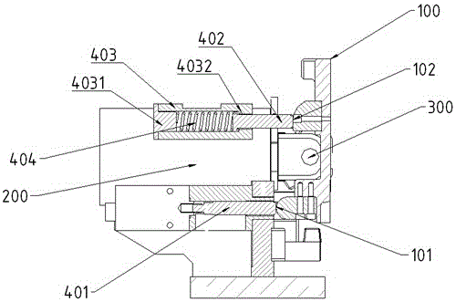
[0023] Embodiment one: see figure 1 , as shown in the legend therein, a flipping mechanism for a side-drawing mold, the side-drawing mold 100 is a movable mold and at least two are arranged, the fixed mold is a bottom mold, and the side-drawing mold 100 has a horizontal opening and closing direction, The main oil cylinder 200 is arranged on the outer surface of the side drawing mold 100, and the driving direction of the main oil cylinder 200 is the same as that of the side drawing mold 100. The outer surface, the outer surface of the side drawing die 100 is provided with a first apex 101 located on the lower side of the rotating shaft 300 and a second apex 102 located on the upper side of the rotating shaft 300, the first apex 101, the rotating shaft 300 and the second apex The part 102 constitutes a lever mechanism, and the turning mechanism includes a turning oil cylinder 401, a push rod 402, a guide sleeve 403 and a pre-tightening return spring 404. The turning 401 is arran...

Embodiment 2

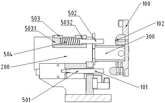
[0035] Embodiment two: see figure 2 , as shown in the legend therein, a flipping mechanism for a side-drawing mold, the side-drawing mold 100 is a movable mold and at least two are arranged, the fixed mold is a bottom mold, and the side-drawing mold 100 has a horizontal opening and closing direction, The main oil cylinder 200 is arranged on the outer surface of the side drawing mold 100, and the driving direction of the main oil cylinder 200 is the same as that of the side drawing mold 100. The outer surface, the outer surface of the side drawing die 100 is provided with a first apex 101 located on the lower side of the rotating shaft 300 and a second apex 102 located on the upper side of the rotating shaft 300, the first apex 101, the rotating shaft 300 and the second apex The part 102 constitutes a lever mechanism, and the turning mechanism includes a first ejector rod 501, a second ejector rod 502, a guide sleeve 503, and a pre-tightening return spring 504. The first eject...


PUM


Abstract

The invention discloses a turnover mechanism of a side-drawing die, wherein the outside of the side-drawing die is provided with a main oil cylinder, the main oil cylinder is hinged to the outer side face of the side-drawing die through a spindle, the outer side face of the side-drawing die is provided with a first vertex part and a second vertex part, the first vertex part, the spindle and the second vertex part form a lever motion, the turnover mechanism comprises a first ejector pin, a second ejector pin, a guide sleeve and a pre-tightening reset spring, the first ejector pin is provided with a first ejector pin face directly facing the first vertex part, the second ejector pin is provided with a second ejector pin face directly facing the second vertex part, the guide sleeve is connected with the second ejector pin in a guiding manner along the die opening and closing direction, and the pre-tightening reset spring is arranged between the bottom of a guide bush of the guide sleeve and the second ejector pin. The turnover mechanism is simple in structure, and has no need of unnecessary dynamic control; during the turnover of the side-drawing die using the turnover mechanism, all points are connected tightly, and the operation is stable.

Description

technical field [0001] The invention relates to a mold opening device for a side-drawing mold, in particular to a turning mechanism for a side-drawing mold. Background technique [0002] The Chinese utility model patent of CN 204262339 U discloses a kind of overturning pouring mould, comprises workbench, fixed mold and at least two movable mold devices, and fixed mold is the bottom mold that is arranged on the workbench, and the movable mold device includes that is arranged on the bottom The side drawing mold on one side of the mold and the main oil cylinder on the driving side are arranged on the workbench. A connecting plate is arranged on the outer surface of the side drawing mold, and the connecting plate is rotatably connected with the driving end of the main oil cylinder and forms a rotation axis; The mold is also equipped with an overturn mechanism, which includes a gear and a rack. The central axis of the gear is coaxial with the rotation axis. The rack extends along...

Claims


Application Information

Patent Timeline
Patent Type & Authority Patents(China)
IPC IPC(8): B29C39/26B29C33/28B22D33/02B22D29/00
Inventor 刘林义王炜斌
Owner SUZHOU MINGZHI TECH
Why Eureka
Try Eureka