Control method, control circuit and switching power supply of isolated converter

A control method and control circuit technology, applied in control/regulation systems, conversion of DC power input to DC power output, instruments, etc., can solve problems such as dynamic responsiveness and stability conflicts, and achieve faster dynamic response speed and lower standby time The effect of loss

Active Publication Date: 2017-06-16
SILERGY SEMICON TECH (HANGZHOU) CO LTD
View PDF8 Cites 0 Cited by
  • Summary
  • Abstract
  • Description
  • Claims
  • Application Information

AI Technical Summary

Problems solved by technology

[0004] In view of this, the present invention provides a control method, control circuit and switching power supply of an isolated converter to solve the problem of conflicting dynamic response and stability in the prior art, and at the same time reduce the problem of standby loss

Method used


Image

  • Control method, control circuit and switching power supply of isolated converter
  • Control method, control circuit and switching power supply of isolated converter
  • Control method, control circuit and switching power supply of isolated converter

Examples


Embodiment Construction

[0044] The following will clearly and completely describe the technical solutions in the embodiments of the present invention with reference to the accompanying drawings in the embodiments of the present invention. Obviously, the described embodiments are only some, not all, embodiments of the present invention. Based on the embodiments of the present invention, all other embodiments obtained by persons of ordinary skill in the art without making creative efforts belong to the protection scope of the present invention.

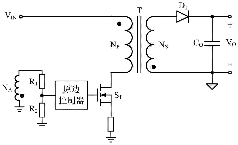
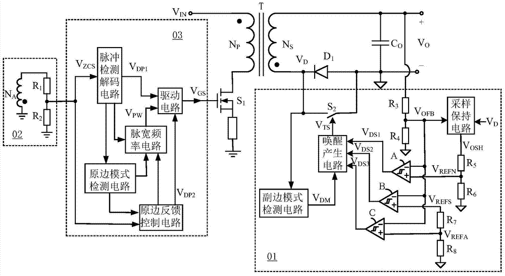
[0045] refer to figure 2 , shows a circuit diagram of an embodiment of a control circuit of an isolated converter according to the present invention. In this embodiment, the isolated converter takes a flyback converter as an example, but it is not limited thereto. The isolated converter receives the input voltage signal V IN , to provide a stable output voltage Vo for the load. Specifically, the flyback converter includes a transformer composed of a primary...


PUM


Abstract

The application provides a control method, a control circuit and a switching power supply of an isolated converter. In the control circuit and method, the wake-up signal is generated by setting different thresholds in different working modes of the isolated converter, so that the drop value of the output voltage of the isolated converter during dynamic loading can be relatively small , to speed up the dynamic response speed of the system, and enable the isolated converter to work at a very low operating frequency during the load steady-state period of the standby mode, effectively reducing the standby loss.

Description

technical field [0001] The invention relates to the field of switching power supplies, more specifically, to a control method, a control circuit and a switching power supply of an isolated converter. Background technique [0002] The switching power supply controlled by the primary side is widely used in the field of power supply such as LED drive power supply, charger and adapter due to the advantages of less system components, simple structure and low cost. [0003] In the primary side control system realized by the existing technology, such as figure 1 As shown, the detection of the output voltage is realized indirectly through the detection of the secondary winding voltage of the transformer. This primary side control system does not detect the output voltage in real time, but only samples the voltage on the auxiliary winding of the transformer in each switching cycle to realize the detection of the output voltage, so that when the output load changes from light load or...

Claims


Application Information

Patent Timeline
Patent Type & Authority Patents(China)
IPC IPC(8): H02M3/335
CPCH02M3/335H02M1/0032H02M1/0048H02M1/08H02M3/33507Y02B70/10
Inventor 张少斌白永江胡志亮李乐董晋平
Owner SILERGY SEMICON TECH (HANGZHOU) CO LTD
Why Eureka
Try Eureka