
A fuel cell heat dissipation system using phase change cooling

A fuel cell and heat dissipation system technology, applied in the direction of fuel cell heat exchange, fuel cells, fuel cell additives, etc., can solve the problems of large coolant flow, large parasitic power of auxiliary systems, etc., and achieve small cooling flow and small parasitic power , the effect of maintaining temperature balance

Active Publication Date: 2017-08-01
KUSN FUERSAI ENERGY
View PDF5 Cites 2 Cited by
  • Summary
  • Abstract
  • Description
  • Claims
  • Application Information

AI Technical Summary

Problems solved by technology

This heat dissipation method has the disadvantages of large coolant flow rate and large parasitic power of the auxiliary system.

Method used


Image

  • A fuel cell heat dissipation system using phase change cooling
  • A fuel cell heat dissipation system using phase change cooling

Examples


Embodiment Construction

[0022] The technical solutions of the present invention will be further described below in conjunction with the accompanying drawings and through specific implementation methods.

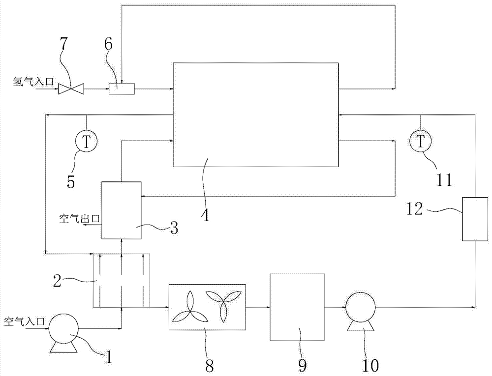
[0023] Such as Figures 1 to 2 As shown, a fuel cell cooling system utilizing phase change cooling includes an electric stack 4, a cathode air supply module connected to the electric stack 4 and used to supply air to the electric stack 4, and also includes a cathode air supply module for cooling the electric stack 4. The electric stack 4 is also a coolant circulation module capable of preheating the air in the cathode air supply module. The fuel cell heat dissipation system using phase change cooling uses the coolant circulation module to cool the inside of the stack, and circulates the heat-absorbed coolant to the air during the cooling of the stack, and the air that will enter the stack Pre-heating is carried out to improve rapid response and efficiency, and maintain the temperature balance in th...


PUM


Abstract

The invention discloses a fuel cell cooling system utilizing phase change cooling. The fuel cell cooling system comprises an electric pile and a cathode air supply module connected to the electric pile and used for supplying the air to the electric pile, and further comprises a cooling liquid circulating module used for cooling the electric pile and preheating the air in the cathode air supply module. The fuel cell cooling system can keep temperature balance in the electric pile, and has the advantages of small cooling flow, small parasitic power of an auxiliary system, waste heat utilization of the cooling liquid and air preheating.

Description

technical field [0001] The invention relates to the technical field of fuel cell heat dissipation, in particular to a fuel cell heat dissipation system utilizing phase change cooling. Background technique [0002] As the global energy crisis becomes more and more serious, and the environmental pollution caused by traditional energy sources intensifies, the application of new energy sources such as natural gas and hydrogen energy has gradually attracted attention. As a new type of energy supply device, fuel cells can efficiently and environmentally friendly convert the chemical energy stored in fuel and oxidant into electrical energy without discharging pollutants. Today, when the environment and energy are of great concern, the development of fuel cells has increasingly attracted the attention of governments and scientific and technological personnel of various countries. [0003] Hydrogen is the best fuel for fuel cells. In the future era of hydrogen economy, fuel cells ar...

Claims


Application Information

Patent Timeline
Patent Type & Authority Patents(China)
IPC IPC(8): H01M8/04
CPCH01M8/04H01M8/04007H01M8/04029Y02E60/50
Inventor 顾荣鑫马天才徐奭戴远行
Owner KUSN FUERSAI ENERGY
Learn More