LED backlight scanning control method and device for liquid crystal display

A liquid crystal display and LED backlight technology, which is applied in the field of backlight system, can solve problems such as screen stripe scrolling, backlight power drop, screen flickering, etc., and achieve the effect of eliminating smear and improving energy efficiency

Inactive Publication Date: 2015-08-12
蔡明雄
View PDF4 Cites 8 Cited by
  • Summary
  • Abstract
  • Description
  • Claims
  • Application Information

AI Technical Summary

Problems solved by technology

None of these technologies can completely solve the smearing phenomenon, and will bring a certain degree of negative impact
[0004] 2. The existing liquid crystal display, after adopting LED backlight, the backlight power will be greatly reduced
[0005] 3. In the prior art, when the backlight scanning method is used for backlight supply, the screen will flicker. The reason is: if figure 2 As shown, the backlight system operates at a fixed frequency f B Scan from top to bottom to illuminate the screen, if the fixed frequency f B There is a phase difference with the frequency of the row pixel writing signal DE, and this phase difference is constantly changing between each row and each frame, indicating that when the backlight illuminates the pixel area of ​​​​the liquid crystal panel, different rows of the same frame The deflection angle of the liquid crystal is different between frames, and between the front and back frames, so the brightness of the light transmitted through the liquid crystal panel is also different, resulting in the phenomenon of scrolling or flickering stripes on the screen.

Method used


Image

  • LED backlight scanning control method and device for liquid crystal display
  • LED backlight scanning control method and device for liquid crystal display
  • LED backlight scanning control method and device for liquid crystal display

Examples


Embodiment 1

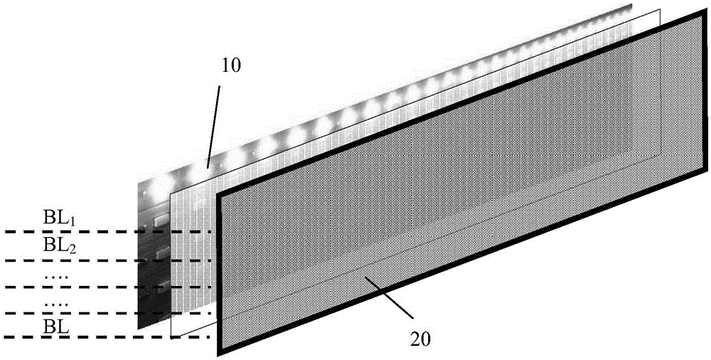
[0038] Please check image 3 , the LED backlight scanning control method of a liquid crystal display, the liquid crystal display has an LED backlight light source 10 and a liquid crystal panel 20, the liquid crystal panel 20 has a pixel resolution of Q rows, and the LED backlight light source includes N independent LED backlight light bars BL 1 , BL 2 ,...,BL M ,...,BL N , the liquid crystal panel is divided into N pixel areas in one-to-one correspondence with the N light bars, and each pixel area corresponds to Q / N rows of pixels.

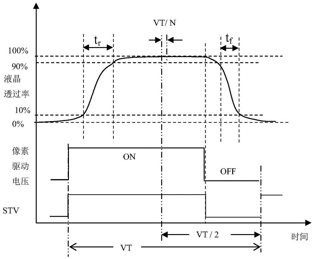
[0039] Please check Figure 4 and Figure 5 , the scan control steps include:

[0040] Step 1, when the detection frame write signal STV is valid, reset and start the delay counter T0, the count value is the first set value, and the range of the first set value can be (0, Q / 2], that is, take half Within a frame period VT / 2, select a specific value according to the needs of the actual liquid crystal display model, preferably, the first set va...

Embodiment 2

[0046] Please check Figure 6 , the LED backlight scanning control device of liquid crystal display, is applicable to the backlight scanning method described in embodiment one, and it comprises:

[0047] a liquid crystal panel, the liquid crystal panel is divided into a plurality of pixel areas;

[0048] LED backlight source, the LED backlight source includes a plurality of independent LED backlight strips 11, and the plurality of LED backlight strips 11 correspond to the plurality of pixel areas one by one;

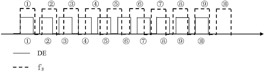
[0049] The backlight address counter 30 is used to capture the frame write signal STV and the row write signal DE and output the address signal of the backlight strip currently to be lit, including a delay counter T0 and a row synchronization counter T1;

[0050] The backlight address decoder 40 is connected to the backlight address counter for decoding the address signal of the backlight strip, and has the number of switch signal output lines matching the number of the...


PUM


Abstract

The invention discloses an LED backlight scanning control method and device for a liquid crystal display. The control method comprises: a step 1 of resetting and starting a delay counter when it is detected that a frame writing signal STV is enabled; a step 2 of resetting and starting a row synchronous counter when the delay counter overflows, and turning on a first light bar when the row synchronous counter overflows; automatically resetting and restarting the row synchronous counter, and turning off the first light bar and turning on a second light bar when the row synchronous counter overflows again; repeating the process and sequentially turning off a prior light bar and turning on a next light bar; and repeating the step 1 and the step 2. The device comprises a liquid crystal panel, an LED backlight light source, a backlight address counter, a backlight address decoder and a switch array module. The liquid crystal panel is divided into a plurality of pixel regions. The LED light source includes a plurality of LED backlight light bars in one-to-one correspondence with the plurality of pixel regions. The method and device provided by the invention has the advantages that: the ghosting phenomena of moving images are completely eliminated, the energy efficiency of the backlight light source is improved, and the flicker of backlight scanning is prevented.

Description

technical field [0001] The invention relates to a backlight system, in particular to an LED backlight scanning control method and device for a liquid crystal display. Background technique [0002] The existing TFT-LCD display adopts LED backlight, the effect is good, the technology is relatively mature, and the original CCFL light source has been completely replaced. But there are still the following problems: [0003] 1. Due to the inertia of the liquid crystal, the dynamic response of the liquid crystal is as follows figure 1 As shown, the response time is long (about 5ms), which causes smearing when displaying moving images; the existing solutions are to use overdrive, black frame insertion technology, motion estimation and compensation technology, and backlight lighting off technology. None of these technologies can completely solve the smearing phenomenon, and will bring a certain degree of negative impact. [0004] 2. In the existing liquid crystal display, after th...

Claims


Application Information

Patent Timeline
Patent Type & Authority Applications(China)
IPC IPC(8): G09G3/34G09G3/36
Inventor 蔡明雄
Owner 蔡明雄
Why Eureka
Try Eureka