Self-balancing reinforced concrete bond and anchor performance tester

A technology of reinforced concrete and anchorage performance, applied in the direction of instruments, measuring devices, and mechanical devices, can solve the problems of increasing unsafe factors, inconvenient test pieces, and difficulty in measuring the bonded stress of steel bars, so as to save manpower and facilitate operation Effect

Active Publication Date: 2017-11-17
CHINA THREE GORGES UNIV
View PDF7 Cites 0 Cited by
  • Summary
  • Abstract
  • Description
  • Claims
  • Application Information

AI Technical Summary

Problems solved by technology

[0003] (1) It is very difficult to measure the slippage at the loading end. At present, there are some problems in the measurement of the slippage of the steel bar at the loading end in the current domestic drawing device because the measured slippage value includes the tensile deformation of the steel bar outside the concrete. big error
[0004] (2) At present, many scientific research institutions need to use external loading equipment such as universal testing machines when doing pull-out tests. Therefore, it is necessary to move the pull-out frame around. The operation is very cumbersome and requires a lot of manpower.
[0005] (3) At present, many drawing frames are used in China, and the specimens are directly exposed outside during the drawing test, which is not convenient for the experimenters to observe the damage development form of the specimens, and also increases certain unsafe factors
[0006] (4) It is very difficult to measure the bond stress of steel bars. The measurement of bond stress in the pull-out test of steel bars has always been a difficult problem for researchers.
[0007] Chinese patent document CN104122201A discloses a reinforced concrete bond stress and slip measurement device, which adopts a structure with displacement sensors, but in this structure, due to the narrow installation space, the installed displacement sensors all adopt a cantilever structure, which affects the measurement accuracy
And special equipment such as universal testing machine is required

Method used


Image

  • Self-balancing reinforced concrete bond and anchor performance tester
  • Self-balancing reinforced concrete bond and anchor performance tester
  • Self-balancing reinforced concrete bond and anchor performance tester

Examples


Embodiment Construction

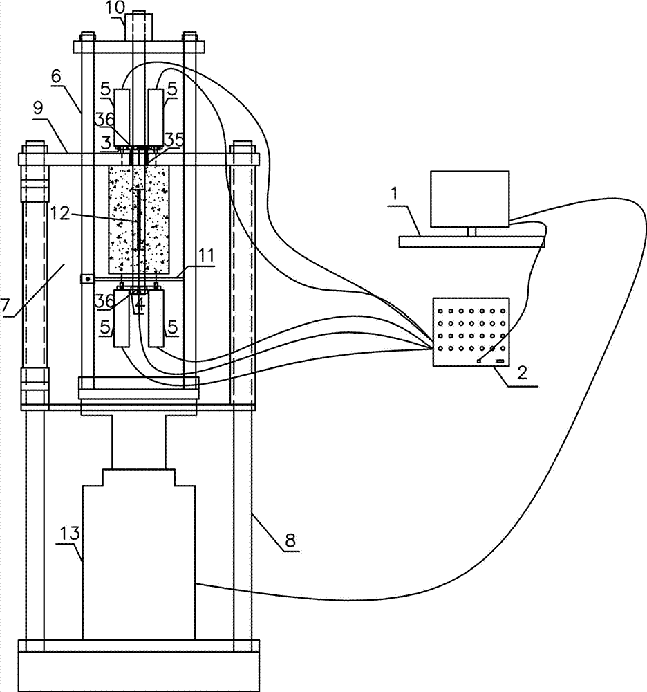
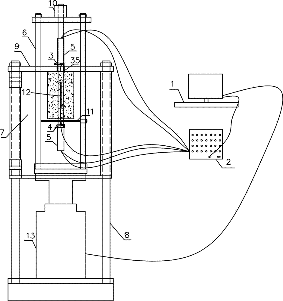
[0036] Such as Figure 1~7 Among them, a self-balancing reinforced concrete bond and anchor performance tester, the inner frame 6 is movably installed on the outer frame top plate 9 of the outer frame 8, the column of the inner frame 6 is slidingly connected with the outer frame top plate 9, and the bottom of the inner frame 6 is set There is a loading device 13 , preferably, the loading device 13 is a hydraulic jack or a screw jack controlled by the computer 1 . In this way, the automatic setting of loading speed and loading force can be realized. The structures of the inner frame 6 and the outer frame 8 are relatively simple, easy to process, and do not need to be anchored, which simplifies the test conditions, and the structure is also convenient for loading the test piece, which simplifies the test steps and improves the test efficiency.

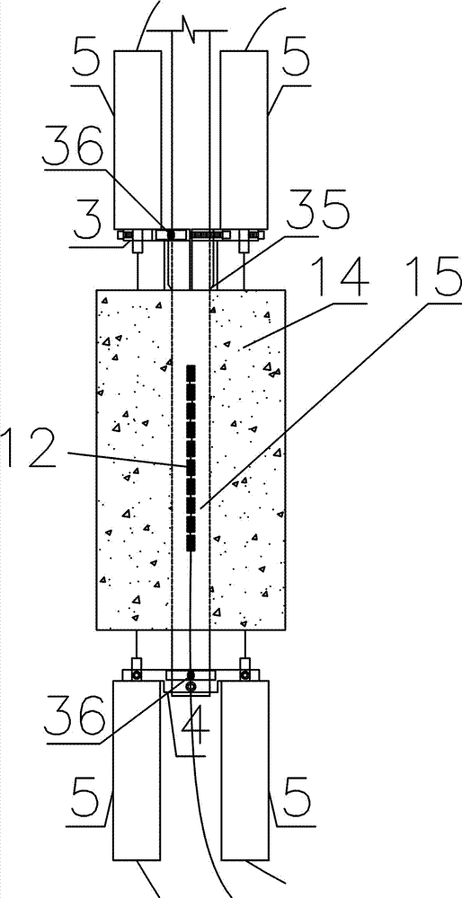
[0037] Such as figure 1 , 2 Among them, the steel bar 15 at the upper end of the test piece slides through the top plate of the out...


PUM


Abstract

A self-balancing reinforced concrete bonding and anchoring performance tester. The inner frame is movably installed on the outer frame top plate of the outer frame. The steel bars slide through the top plate of the outer frame and the top plate of the inner frame and are connected with nuts; the steel bars at both ends of the specimen are provided with a loading end fixing device and a free end fixing device, and each of the loading end fixing device and the free end fixing device is equipped with at least one The displacement meter, the measuring rod of the displacement meter is in contact with the end face of the concrete of the specimen. A plurality of strain gauges are provided on the steel bars in the concrete. By adopting the unique design of the loading end fixing device and the free end fixing device, the invention can tightly fix the displacement meter at the loading end and the free end of the test piece, and fix the loading end fixing device at the intersection of the steel bar and the concrete in the test piece. At the interface, the slippage of the free end and the loading end of the specimen can be accurately measured during the loading process.

Description

technical field [0001] The utility model relates to the field of civil engineering bonding and sliding performance tests, in particular to a self-balancing reinforced concrete bonding and anchoring performance tester. Background technique [0002] Bond-slip behavior is one of the most important fundamental issues in the theory of reinforced concrete structures. At present, the bond test methods used include pull-out test, beam test and axial pull test. The preparation of the test piece and the test device for the pull-out test are relatively simple, and the test results are easy to analyze. Therefore, it has been used as a benchmark for relative comparison of the bond performance of steel bars for a long time. In order to achieve the bond-slip τs For a more precise description of the constitutive relationship, the method of rebar slotting, patching, and calculation of internal slip distribution from the loaded end and free end is often used to explore bonded anchorage τs...

Claims


Application Information

Patent Timeline
Patent Type & Authority Patents(China)
IPC IPC(8): G01N19/04
Inventor 徐港张小龙王青卫泽众潘琪徐丽丽
Owner CHINA THREE GORGES UNIV
Why Eureka
Try Eureka