Composite insulator dynamic load torsional vibration testing machine

A technology for composite insulators and dynamic loads, applied in vibration testing, testing of machine/structural components, measuring devices, etc., can solve problems such as complexity, broken mandrels, and inaccurate damage mechanisms of insulators

Active Publication Date: 2017-05-03
CHINA THREE GORGES UNIV
View PDF4 Cites 0 Cited by
  • Summary
  • Abstract
  • Description
  • Claims
  • Application Information

AI Technical Summary

Problems solved by technology

[0002] At present, there is no experimental machine that can systematically study the damage mechanism of insulators. Many studies have only theoretically pointed out that composite insulators under natural working conditions often have flashovers, aging, slipping and falling off of fittings, mandrel breakage, Faults such as hardware damage are mainly caused by the combination of a series of factors such as the insulator bearing the load of the wire (including the weight of ice coating), the dynamic load caused by wind vibration, the uneven electric field, and the corrosion of environmental pollution.
At present, the testing machine designed by some scholars to explore the damage mechanism of composite insulators only considers the damage status of the insulator under some single factors such as tension or torque. However, the influencing factors of real working conditions are more complicated than these experimental working conditions. much
At the same time, the wind load and ice load are random in actual conditions. If only constant or periodic loads are used for simulation, the obtained results are not accurate enough to describe the damage mechanism of insulators.

Method used


Image

  • Composite insulator dynamic load torsional vibration testing machine
  • Composite insulator dynamic load torsional vibration testing machine
  • Composite insulator dynamic load torsional vibration testing machine

Examples


Embodiment Construction

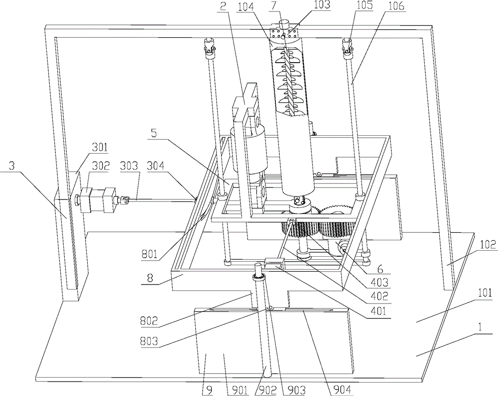
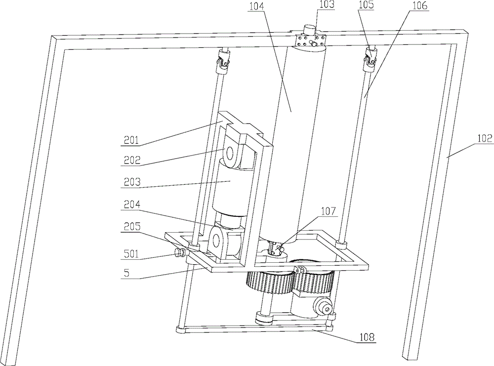
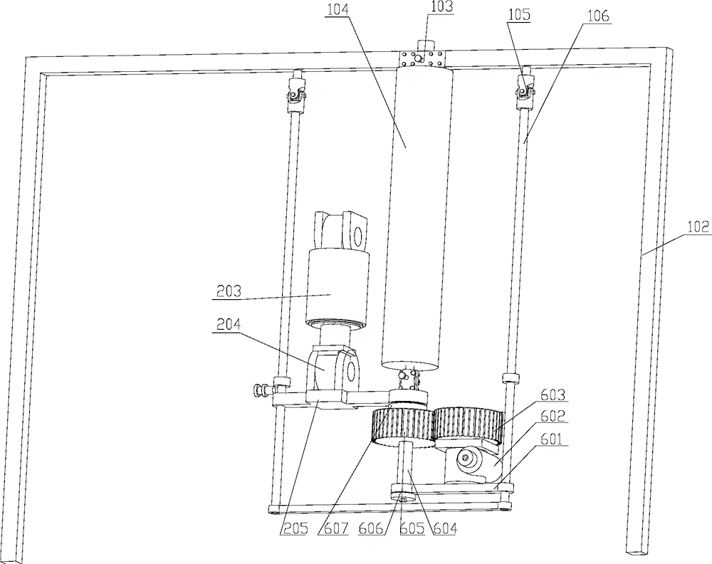
[0042] Embodiments of the present invention will be further described below in conjunction with the accompanying drawings.

[0043] see Figure 1-8 , a composite insulator dynamic load torsional vibration testing machine, which includes a frame device 1, an insulator sleeve 104 is vertically installed on the bracket 102 of the frame device 1, and a torsional load device 6 is installed at the bottom of the insulator sleeve 104, and the torsional load The device 6 is connected to the swing rod 106 of the frame device 1 through the support plate 601, the inner swing frame 5 is connected on the swing rod 106, the tensile load device 2 is installed on the inner swing frame 5 through the stretch bracket 201, and the inner swing frame 5 One side of the outer swing frame 8 is connected with the outer swing frame 8 through the sliding pin 501, and the left and right swing load device 3 is connected to the left outer surface of the outer swing frame 8, and the left and right swing load ...


PUM


Abstract

The invention relates to a composite insulator dynamic load torsional vibration testing machine, comprising a frame device, a tensile load device, a left and right oscillating load device, a back and forth oscillating load device, an inner oscillating rack, a torsional load device, a composite insulator, an outer oscillating frame and a slide rail. The tensile load device provides a tensile load. The left and right oscillating load device and the back and forth oscillating load device provide a left and right oscillating load and a back and forth oscillating load respectively. The torsional load device provides a torsional load. The abovementioned loads can be added in an independent or combined manner, so that the dynamic load torsional vibration test is performed on the composite insulator. After the testing machine completes the test, damage parts, damage degrees and microstructures of damage areas under a scanning electron microscope are observed, other mechanics performance tests are carried out, and experiment results under different experiment conditions are compared and analyzed so as to study influences of various factors under a practical working condition on damage conditions of the insulator.

Description

technical field [0001] The invention relates to a composite insulator performance testing machine, in particular to a composite insulator dynamic load torsional vibration testing machine. Background technique [0002] At present, there is no experimental machine that can systematically study the damage mechanism of insulators. Many studies have only theoretically pointed out that composite insulators under natural working conditions often have flashovers, aging, slipping and falling off of fittings, mandrel breakage, Faults such as hardware damage are mainly caused by the combination of a series of factors such as the insulator bearing the load of the wire (including the weight of ice coating), the dynamic load caused by wind vibration, the uneven electric field, and the corrosion of environmental pollution. At present, the testing machine designed by some scholars to explore the damage mechanism of composite insulators only considers the damage status of the insulator under...

Claims


Application Information

Patent Timeline
Patent Type & Authority Patents(China)
IPC IPC(8): G01M7/06
Inventor 赵新泽汪坤付志成徐翔赵美云秦红玲王佳乐王磊陈柯柯鲜于文玲
Owner CHINA THREE GORGES UNIV
Why Eureka
Try Eureka