Eureka AIR delivers breakthrough ideas for toughest innovation challenges, trusted by R&D personnel around the world.

Sliding contact moving conduction device

A conductive device, sliding contact technology, applied in the direction of circuits, current collectors, electrical components, etc., can solve the problems of unstable power transmission, running track deviation, separation and so on

Inactive Publication Date: 2012-02-15
江苏江鹤滑线电气有限公司
View PDF5 Cites 10 Cited by
  • Summary
  • Abstract
  • Description
  • Claims
  • Application Information

AI Technical Summary

Problems solved by technology

[0003] However, in practical applications, frequent driving and trolleys cause unstable operation due to the suspension of goods; resulting in deviation and separation of the running track between the brush on the collector and the trolley line, resulting in instantaneous power failure, unstable power transmission, etc. problems; once these problems occur, there will be operational failures at least, and even cause personal injury

Method used


Image

  • Sliding contact moving conduction device
  • Sliding contact moving conduction device
  • Sliding contact moving conduction device

Examples


Embodiment Construction

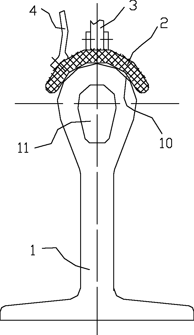
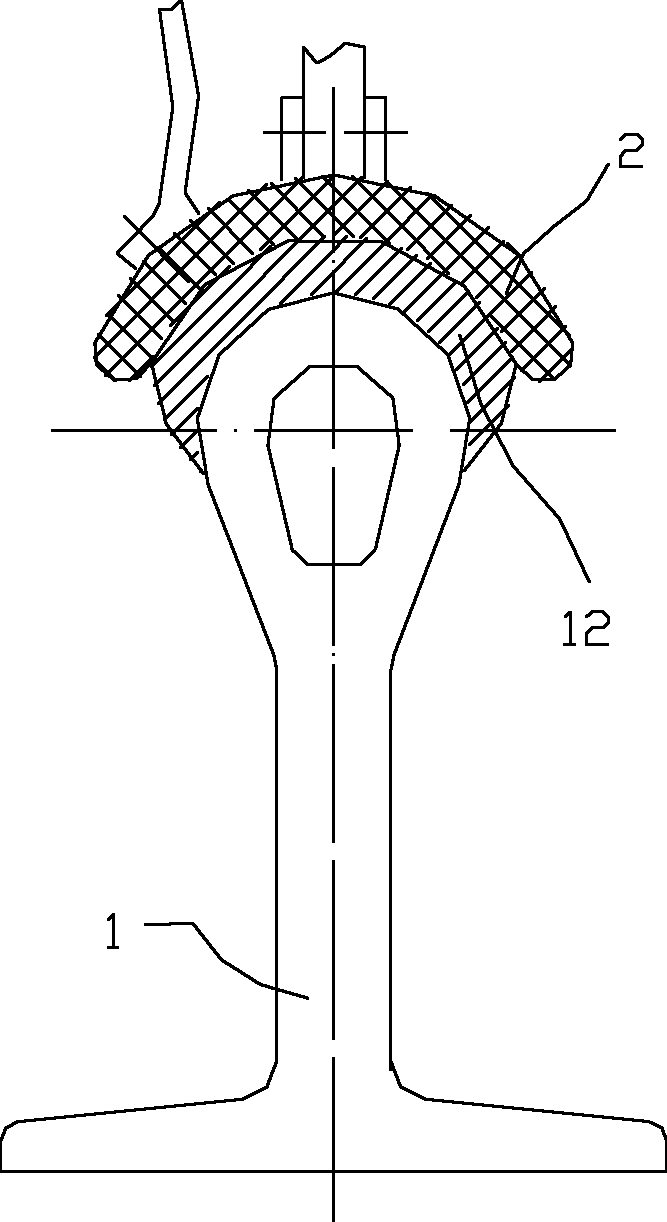
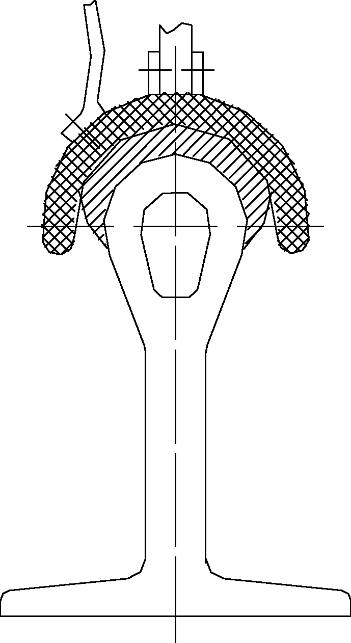
[0019] Such as Figure 1-4 As shown, the present invention includes a trolley line 1, a guide rail and a running part provided with a collector, the trolley line 1 has a conductive working surface 10, and the trolley line 1 is parallel to the guide rail; the running part is along the The guide rail runs; the collector includes a collector arm 3, a brush 2, a conductive strip 4 and a bottom plate, and the bottom plate is fixedly connected to the moving part; the working surface of the brush 2 contacts the sliding contact line working face 10;

[0020] From the cross section, the working surface of the trolley line 1 is convex arc-shaped;

[0021] From the cross section, the working surface of the brush 2 is in a concave arc shape consistent with the working surface 10 of the trolley line.

[0022] The convex arc shape of the trolley line working surface 10 is a circular arc shape.

[0023] The convex arc of the working surface of the trolley line is a superior arc larger tha...


PUM


Abstract

The invention relates to a trolley conductor and a collector applied to unbalance loading and curve places, and provides a sliding contact moving conduction device still capable of keeping normal power supply between an electric brush and the trolley conductor when a balance loading force is generated. The device comprises the trolley conductor, a guide rail and a running part with a collector. By the device, a conventional plane contact designing scheme in the field is changed, the electric brush is improved into a tile shape, and a trolley conductor working surface is changed into an arc shape, so a centrifugal force which is an unbalance loading force for the electric brush and is caused by the automatic generation of a centrifugal force at a curve of a production line can be overcome to a certain extent; and when the unbalance loading force is relatively stronger, an electric brush working surface is preferably arched, so that an 'enveloping' effect can be achieved for the trolley conductor working surface to prevent the electric brush from sliding out of the guide rail. By the device, stable power transmission is ensured, and simultaneously, the electric brush can be ensured not to be deviated and separated from the trolley conductor to further improve the running safety, stability and reliability of equipment.

Description

technical field [0001] The invention relates to a trolley line and a current collector with both power supply guiding functions, in particular to a trolley line and a current collector applied to the occasions of eccentric loads and curved roads. Background technique [0002] In many occasions, it is necessary to transmit electric energy to moving parts, such as driving, running trolleys on automated production lines, etc. Generally, the track of the driving or trolley is set on the fixed structure, and then the charged trolley line is arranged parallel to the track; then, the collector on the trolley and the trolley receives electric energy through contact with the trolley line, and provides the running power of the trolley and trolley source. [0003] However, in practical applications, frequent driving and trolleys cause unstable operation due to the suspension of goods; resulting in deviation and separation of the running track between the brush on the collector and the...

Claims


Application Information

Patent Timeline
Patent Type & Authority Applications(China)
IPC IPC(8): H01R41/00
Inventor 华鹤章董永军
Owner 江苏江鹤滑线电气有限公司
Why Eureka
Eureka Blog
Learn More