
Tailcone forming mould and forming method of tailcone forming mould

A technology for forming molds and tail cones, applied in the field of aero-engines, can solve the problems of irregular shape of the blank, skewed top of the blank, extrusion of superimposed parts, etc., so as to reduce waste, improve yield, and prevent excessive stretching and extrusion. Effect

Active Publication Date: 2015-08-12
CHINA HANGFA SOUTH IND CO LTD
View PDF7 Cites 8 Cited by
  • Summary
  • Abstract
  • Description
  • Claims
  • Application Information

AI Technical Summary

Problems solved by technology

[0004] The invention provides a tail cone molding die and its molding method to solve the problem of the irregular shape of the molding blank in the prior art, which cannot be accurately positioned and causes the top of the blank to be skewed after the blank is formed. The technical problem that the material may be extruded and superimposed to cause the scrapping of the part

Method used


Image

  • Tailcone forming mould and forming method of tailcone forming mould
  • Tailcone forming mould and forming method of tailcone forming mould
  • Tailcone forming mould and forming method of tailcone forming mould

Examples


Embodiment Construction

[0032] The embodiments of the present invention will be described in detail below with reference to the accompanying drawings, but the present invention can be implemented in many different ways defined and covered by the claims.

[0033] Unless otherwise specified, the technical means used in the embodiments are conventional means well known to those skilled in the art. The mold provided by the invention is not limited to tail cone molding for aero-engines, and can also be used in other conical surface molding parts. However, it is preferably used in aero-engines. At this time, the molding efficiency is high, and parts with conical surfaces, excessively arcuate surfaces and cylindrical surfaces can be obtained at one time.

[0034] see Figure 6, the tail cone forming mold provided by the present invention includes a lower template 100, an upper template 900, a die 600, and a punch 500 whose center lines are overlapped, and a forming groove 610 is arranged at the center of t...


PUM


Abstract

The invention provides a tailcone forming mould which comprises a lower mould plate, an upper mould plate, a concave mould body and a convex mould body. The central lines of the lower mould plate, the upper mould plate, the concave mould body and the convex mould body are coincided with each other, a forming groove is formed in the center of the concave mould body, the convex mould body is fixedly arranged on the top surface of the lower mould plate, and the concave mould body is arranged under the bottom surface of the upper mould plate. The tailcone forming mould further comprises limiting columns for controlling the downward moving distance of the concave mould body, an edge pressing ring in contact with the inner lateral wall of the forming groove and a plurality of ejector rods which can enable the edge pressing ring and the forming groove to clamp a formed workblank; the ejector rods are respectively arranged on the lower mould plate and evenly distributed around the convex mould body in the peripheral direction; the ejector rods abut against the bottom edge of the edge pressing ring and can drive the edge pressing ring and the formed workblank; the at least two limiting columns are evenly distributed between the edge pressing ring and the lower mould plate; the height difference between the top surfaces of the limiting columns and the bottom surface of the edge pressing ring can be determined by the distance between the top end of the formed worblank and a conical face of the convex mould body in the vertical direction. According to the tailcone mould, the rate of finished products of tailcones can be improved to 100% from 50%, the percent of pass is verified repeatedly, and the effect is stable.

Description

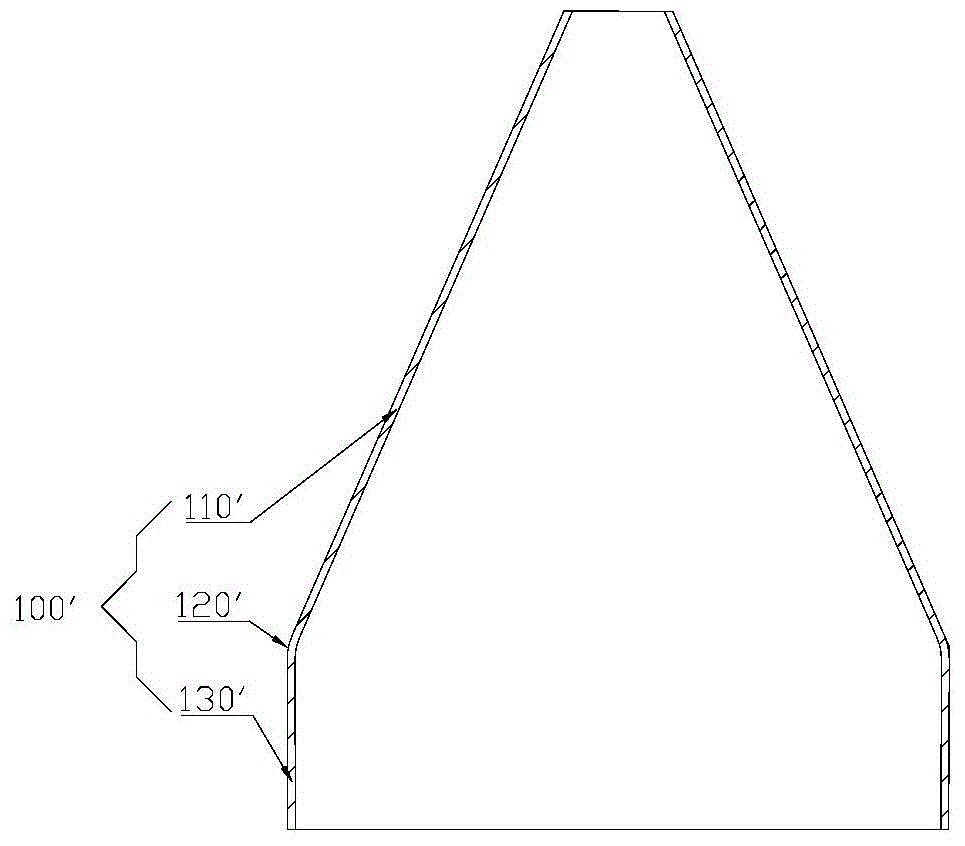
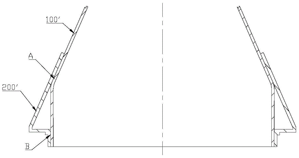
technical field [0001] The invention relates to the field of aero-engines, in particular to a tail cone molding die and a molding method thereof. Background technique [0002] Tail cone parts are commonly used in aero-engines. The structure of the tail cone can be a single conical surface or a tail cone that includes a conical surface, a transitional arc surface and a cylindrical surface. Such as figure 1 The shown tail cone 100' includes a conical surface 110', a transition arc surface 120' and a cylindrical surface 130' at the same time. When the tail cone 100' is in use, it is often necessary to weld the two ends of the part to parts such as mounting edges. Welded assembly such as figure 2 As shown, tail cone 100' is inserted into part 200' to be welded. The welding points of the tail cone 100' and the parts to be welded 200' are A and B (places A and B are actually the joint surfaces of the tail cone 1' and the parts to be welded 2'). A is spot welding and B is sea...

Claims


Application Information

Patent Timeline
Patent Type & Authority Applications(China)
IPC IPC(8): B21D37/10B21D22/22
CPCB21D22/22B21D37/10
Inventor 李又春李玲向建华
Owner CHINA HANGFA SOUTH IND CO LTD
Learn More