
A pipe left and right bending mechanism

A technology for bending and pipe bending, which is applied in the field of left and right bending mechanisms for pipes, can solve the problems of high cost, long time consumption, cumbersome bending process, etc., and achieve the effect of simple structure and high work efficiency.

Active Publication Date: 2017-03-22
FOSHAN TIANJIAN MECHANICAL CO LTD
View PDF6 Cites 0 Cited by
  • Summary
  • Abstract
  • Description
  • Claims
  • Application Information

AI Technical Summary

Problems solved by technology

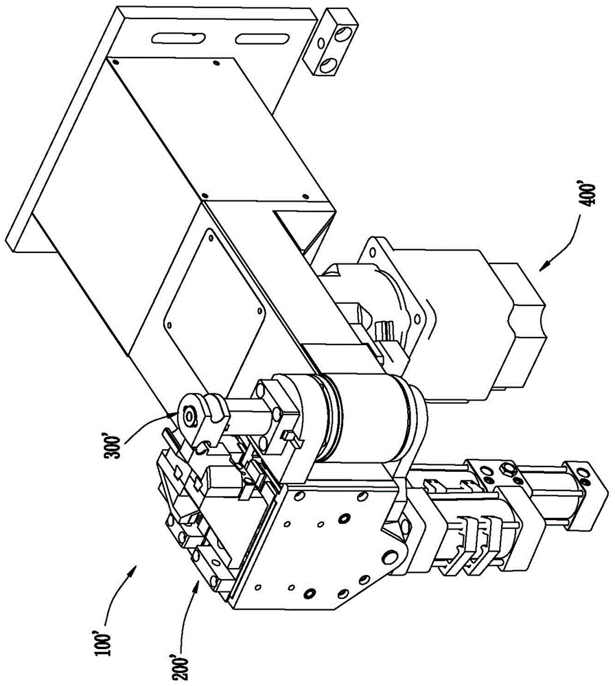
For copper pipes that need to be bent in different directions multiple times, the use of the existing bending machine 100' will make the entire bending process too cumbersome, time-consuming, and the quality of the bending cannot be effectively guaranteed. In addition, the entire bending The structure of the forming machine 100' is also too complicated and the cost is high

Method used


Image

  • A pipe left and right bending mechanism
  • A pipe left and right bending mechanism
  • A pipe left and right bending mechanism

Examples


Embodiment Construction

[0021] Below in conjunction with specific embodiment, the present invention will be further described:

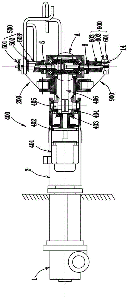
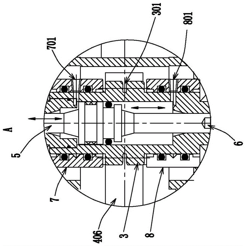
[0022] see attached figure 2 to the attached Figure 4 As shown, a bending mechanism 100 for bending pipes left and right described in this embodiment includes a head base 2 and a circular cylinder 3 rotatably connected to the front end of the head base 2. And the turning unit 1 connected to the end of the head base 2 and used to drive the turning unit 1 to be turned 180°. In this embodiment, the turning unit 1 preferably adopts a hydraulic rotary cylinder. Wherein, the hydraulic rotary cylinder is also connected with the head base 2 through a fixed transition seat 13 fixed on the body of the bending machine (ie, the body used for installing the bending mechanism in this solution). The upper and lower ends of the circular cylinder 3 are also respectively fixed with a right bending die assembly 500 for bending the pipe to the right and a left bending die assembly 600 for ...


PUM


Abstract

The invention relates to a left and right elbow bending mechanism for a pipeline. The left and right elbow bending mechanism comprises an overturning unit for driving a headstock to be overturned by 180 degrees, a cylinder barrel which is rotatably connected with the headstock in a vertical direction, a driving unit which is fixed on the headstock and is used for driving the cylinder barrel to rotate positively and negatively, a pair of upper piston rod and lower piston rod which are respectively arranged in the upper part and the lower part of an inner cavity of the cylinder barrel, a right elbow die assembly and a left elbow die assembly which are respectively arranged on the upper end and the lower end of the cylinder barrel, as well as a right elbow profiling assembly and a left elbow profiling assembly which are respectively fixed on the upper end and the lower end of the headstock and are matched with the right elbow die assembly and the left elbow die assembly to realize pipeline bending; a pair of upper hydraulic rotation connector and lower hydraulic rotation connector which are rotatably communicated with the upper part and the lower part of the inner cavity of the cylinder barrel respectively are arranged on the outer side of the cylinder barrel; when the cylinder barrel rotates positively and negatively, the upper hydraulic rotation connector and the lower hydraulic rotation connector are correspondingly communicated with the upper part and the lower part of the inner cavity of the cylinder barrel. The left and right elbow bending mechanism can realize relatively low cost and high working efficiency and is capable of rapidly realizing the purpose of bending a copper pipe in different directions.

Description

technical field [0001] The invention relates to the technical field of pipe bending equipment, in particular to a left and right bending mechanism for pipes. Background technique [0002] In the refrigeration industry, refrigeration copper tubes are a common refrigeration accessory, mainly used for the circulation of refrigerants; however, copper tubes are usually continuously bent for many times during use to control the flow rate of the refrigerant in them. and traffic. When the existing copper pipe is subjected to multiple continuous bending operations in different directions, it is generally carried out by a set of bending machines with a steering mechanism for steering the copper pipe, which can only be bent in a single direction. Curved work. see attached figure 1 Shown is a schematic diagram of the structure of the existing one-way bending machine 100' (the steering mechanism on the existing one-way bending machine is not shown), and the existing one-way bending ma...

Claims


Application Information

Patent Timeline
Patent Type & Authority Patents(China)
IPC IPC(8): B21D7/06B21D43/00B21D37/10
CPCB21D7/06B21D37/10B21D43/003
Inventor 黄伟明
Owner FOSHAN TIANJIAN MECHANICAL CO LTD
Learn More