Lift-type smoke-eliminating ceiling screen
A smoke-blocking vertical wall, lift-type technology, applied in medical science, dentistry, dental drilling, etc., can solve the problems of inability to eliminate smoke, and the smoke-blocking vertical wall occupies a large space.
- Summary
- Abstract
- Description
- Claims
- Application Information
AI Technical Summary
Problems solved by technology
Method used
Image
Examples
Embodiment 1
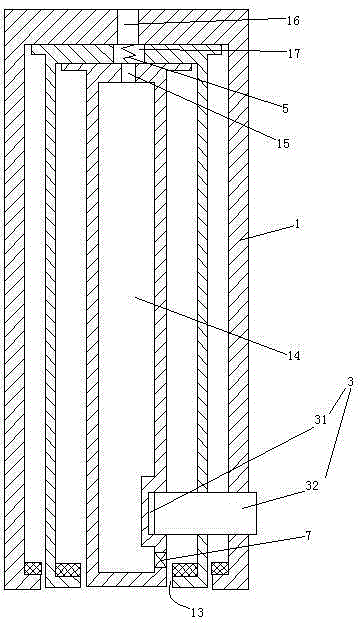
[0023] Embodiment one, see figure 1 , a lift-type smoke-elimination and smoke-blocking vertical wall, including three smoke-blocking boards 1 arranged sequentially from top to bottom (designing two pieces can realize shrinkage, but when the height of the smoke-blocking vertical wall is constant, the smoke-blocking The greater the number of boards, the shorter the time required for fully unfolding, that is, the faster the response speed). Therefore, the length of the smoke baffle 1 (dimensions in the left and right directions in the figure) is equal, of course, as long as the length of the longest smoke baffle minus the length of the shortest smoke baffle is 5mm As follows, the left and right ends of the present invention can conveniently realize no smoke leakage or less smoke leakage.
[0024] see figure 2 , The smoke baffle 1 is provided with a socket 31 . The lower end of the smoke baffle 1 is provided with an inner flange 11 . The upper end of the smoke baffle 1 is pro...
Embodiment 2
[0029] Embodiment two, the difference with embodiment one is:
[0030] see Figure 4, The retracted position maintaining structure 3 includes a barb 33 and a hinge shaft 34 . The barb 33 hooks the lower end of the lowermost smoke baffle in the smoke baffle 1 . The upper end of the barb 33 is hinged to the connecting ear 18 in the uppermost smoke baffle 1 through the hinge shaft 34 .
[0031] When the present invention is to be stretched out to realize the smoke baffle, the barb 33 is rotated clockwise around the hinge shaft 34 until it loses the hooking effect on all the smoke baffles 1 .
Embodiment 3
[0032] Embodiment three, the difference with embodiment three is:
[0033] see Figure 5 , The barb 33 is fixedly connected with the hinge shaft 34. The hinge shaft 34 is rotatably connected to the connecting ear 18 . The uppermost smoke baffle 1 is pierced with a rack 4 . The rack 4 is driven by a motor to realize translation. The hinge shaft 34 is provided with a drive gear 6 . The drive gear 6 meshes with the rack 4 . Several lubricating mechanisms 8 are arranged in the driving gear 6 . The number of lubricating mechanisms 8 is equal to the number of teeth of the driving gear 6 .
[0034] see Figure 6 , The lubricating mechanism 8 includes an oil outlet 81 , an air supply port 82 , a sealing head 83 , a first spring 84 , a cylinder 85 and a piston 86 . The oil outlet 81 and the air supply port 82 of the same lubricating mechanism are arranged on the tooth top 61 of the same tooth of the driving gear 6, and only one oil outlet and the air supply port of the lubricat...
PUM
 Abstract
Description
Claims
Application Information
 - R&D
- Intellectual Property
- Life Sciences
- Materials
- Tech Scout
- Unparalleled Data Quality
- Higher Quality Content
- 60% Fewer Hallucinations
Browse by: Latest US Patents, China's latest patents, Technical Efficacy Thesaurus, Application Domain, Technology Topic, Popular Technical Reports.
© 2025 PatSnap. All rights reserved.Legal|Privacy policy|Modern Slavery Act Transparency Statement|Sitemap|About US| Contact US: help@patsnap.com


