
Electric vacuum cleaner

A vacuum cleaner and electric technology, applied in the direction of vacuum cleaners, suction filters, chemical instruments and methods, etc., can solve problems such as leakage, insufficient sound insulation of noise, and large diameter of the surrounding wall

Active Publication Date: 2015-08-05
TOSHIBA LIFESTYLE PROD & SERVICES CORP
View PDF7 Cites 69 Cited by
  • Summary
  • Abstract
  • Description
  • Claims
  • Application Information

AI Technical Summary

Problems solved by technology

In this case, the peripheral wall portion of the cylindrical centrifugal separation part is disposed coaxially with respect to the central axis of the electric blower, so the air intake is less likely to be deflected, and although the air intake balance can be ensured, the centrifugal separation part must Coarse dust, which is relatively large dust in dusty air, is centrifugally separated, so the diameter of the surrounding wall must be set large, and miniaturization is not easy
In addition, around the electric blower chamber, there is basically only the peripheral wall of the centrifugal separation unit, so noise such as wind howling generated by driving the electric blower is not sufficiently sound-proofed, and may leak to the outside.

Method used


Image

  • Electric vacuum cleaner
  • Electric vacuum cleaner
  • Electric vacuum cleaner

Examples


Embodiment Construction

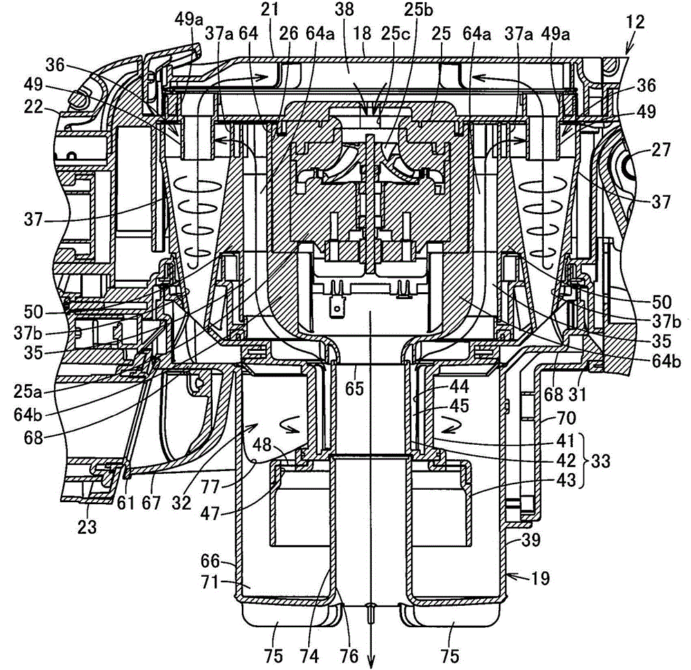
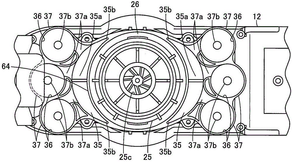
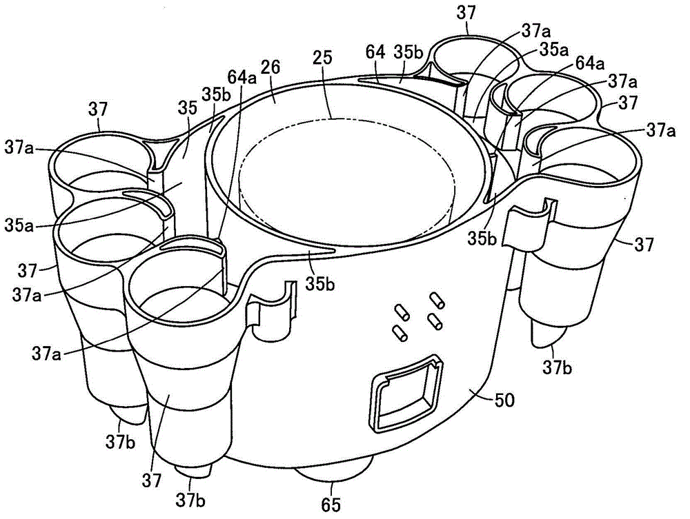
[0022] Below, refer to Figure 1 to Figure 10 The configuration of the first embodiment will be described.

[0023] exist Figure 1 to Figure 10 Among them, 11 represents an electric vacuum cleaner, and the electric vacuum cleaner 11 can be arbitrarily selected such as Figure 6 to Figure 10 How to use it as a stick type vacuum cleaner (upright vacuum cleaner) while moving the whole body as shown and how Figure 4 and Figure 5 As shown, it is a mode of using it as a hand-held vacuum cleaner while carrying a part.

[0024] and, if Figure 1 to Figure 10 As shown, the electric vacuum cleaner 11 has a main body 12 and an air passage body 13 connected to the main body 12. The air passage body 13 can be held on the main body 12 by a holding part 14, and a main body is protruded from the main body 12. The air passage body handle 17 is protrudingly provided on the air passage body 13 using the handle 15 . In addition, below, the up-down direction is based on the state which mo...


PUM


Abstract

 Provided is an electric vacuum cleaner in which quietness can be improved without increasing size while air-intake balance is guaranteed. The electric vacuum cleaner has an electric air blower (25). The electric vacuum cleaner has a separating section (39) for separating dust drawn in by the electric air blower (25). The separating section (39) is provided with a first centrifugal separating section (32) for centrifugally separating dust drawn in by the electric air blower (25). The separating section (39) is provided with a plurality of second centrifugal separating sections (36) for centrifugally separating dust that is smaller than the dust separated in the first centrifugal separating section (32). The second centrifugal separating sections (36) are in communication with the downstream side of the first centrifugal separating section (32), and are respectively arranged in positions on opposite sides of the electric air blower (25).

Description

technical field [0001] Embodiment of this invention relates to the electric vacuum cleaner provided with the centrifugal separation part which centrifugally separates the dust sucked by the electric blower. Background technique [0002] Conventionally, for example, an electric vacuum cleaner that can be carried and cleaned has a main body including an electric blower, a dust collecting unit, and the like, and an air passage body such as an extension pipe connected to the main body. Then, while holding the grip handle of the main body to carry the whole electric vacuum cleaner, dust is sucked from the air passage body into the dust collecting part by the negative pressure generated by driving the electric blower to perform cleaning. [0003] The dust collecting unit of such an electric vacuum cleaner includes a centrifugal separation unit that rotates dust-laden air to centrifugally separate dust, and an electric blower chamber for accommodating an electric blower is arranged...

Claims


Application Information

Patent Timeline
Patent Type & Authority Applications(China)
IPC IPC(8): A47L9/16
CPCA47L5/24A47L9/1633A47L9/1641A47L9/0081A47L5/225A47L5/28A47L9/16A47L9/1608A47L9/1625A47L9/1658A47L9/1691A47L9/22B01D45/16
Inventor 川村直子大津育弘町田幸雄井上勉森下笃至
Owner TOSHIBA LIFESTYLE PROD & SERVICES CORP
Learn More