
Rubber belt cooling production line

A production line and rubber belt technology, applied in the field of rubber belt cooling production line, can solve the problems of high labor intensity, affecting the cutting procedure, and low cooling effect, and achieve the effect of reducing labor intensity, good cooling effect, and ensuring cooling effect.

Inactive Publication Date: 2015-08-05
安徽省潜山市创先实业有限公司
View PDF6 Cites 1 Cited by
  • Summary
  • Abstract
  • Description
  • Claims
  • Application Information

AI Technical Summary

Problems solved by technology

In the prior art, when cooling the extruded rubber belt, the operator needs to manually put the high-temperature extruded rubber belt into the cooling water tank. The labor-intensive and high-temperature rubber belt is easy to burn the operator, and many rubber belts When cooling together, two adjacent rubber belts are prone to sticking and mixing together, which will affect the follow-up work and cause unnecessary troubles; in addition, the water in the cooling water tank will have the temperature of the cooling water during the long cooling process. When the cooling effect becomes lower due to rising, and after the rubber belt is cooled by cooling water, the rubber belt will be stained with cooling water, which will directly enter the cutting device for cutting, which will affect the cutting process

Method used


Image

  • Rubber belt cooling production line
  • Rubber belt cooling production line
  • Rubber belt cooling production line

Examples


Embodiment Construction

[0013] The present invention will be further described below in conjunction with the embodiments and the accompanying drawings.

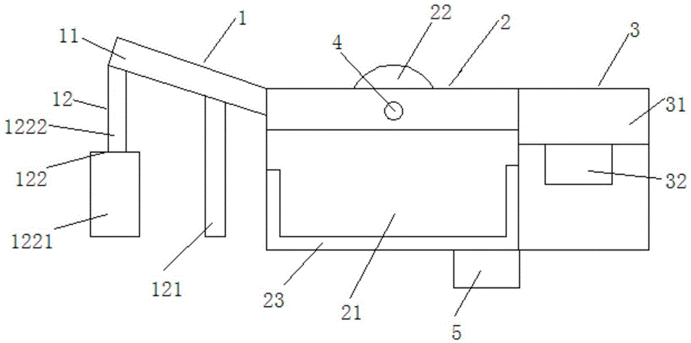
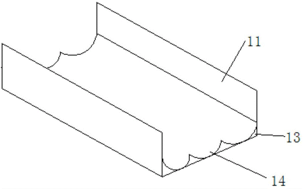
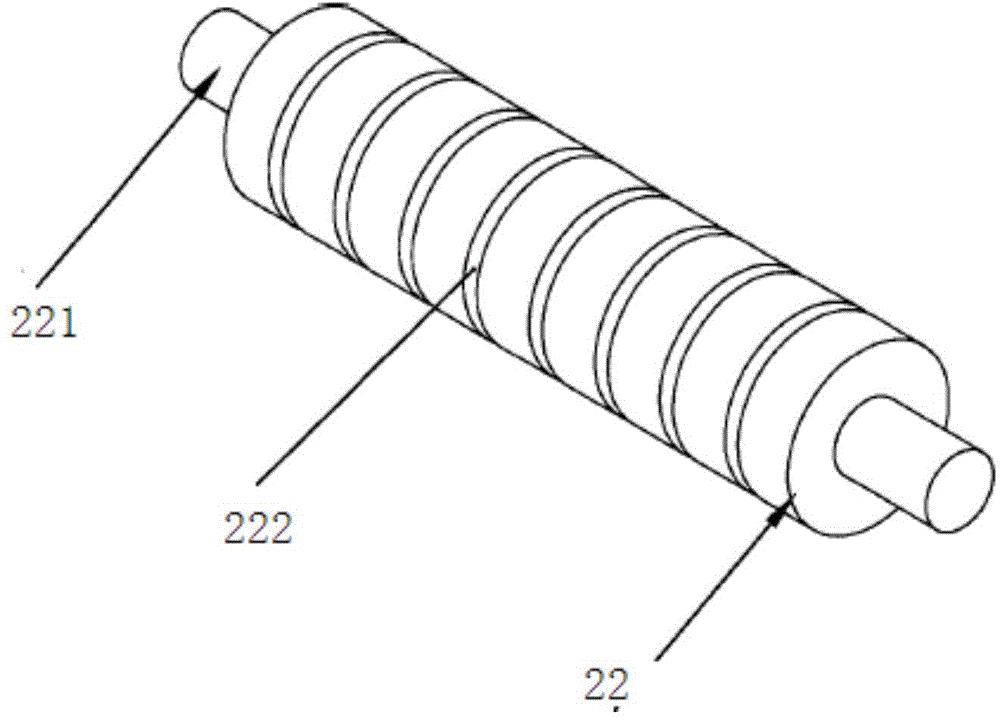
[0014] See attached figure 1 , attached figure 2 And attached image 3 , a rubber belt cooling production line, comprising a material introduction device 1, a cooling device 2 and an air-drying device 3, the material introduction device 1 is arranged in front of the cooling device 2, and the air-drying device 3 is arranged behind the cooling device 2, and the material introduction device 1 includes a material introduction Plate 11 and support column 12, conveyer belt 13 is provided on the feeder plate 11, and the surface of conveyer belt 13 is provided with arc-shaped material introduction groove 14, and described support column 12 comprises fixed column 121 and the adjustment column 122 that can adjust height, The adjustment column 122 includes a fixed seat 1221 and a telescopic rod 1222. The cooling device 2 includes a cooling water tank 21, a ...


PUM

PropertyMeasurementUnit
depthaaaaaaaaaa

Abstract

The invention discloses a rubber belt cooling production line. The rubber belt cooling production line comprises a material guide device, a cooling device and a drying device; the material guide device is arranged in front of the cooling device; the drying device is arranged behind the cooling device; the material guide device comprises a material guide plate and a supporting column; the material guide plate is provided with a conveyor belt; the surface of the conveyor belt is provided with a circular-arc-shaped material guide groove; the cooling device comprises a cooling water tank, a conveying drum and cooling pipes; the side wall of the conveying drum is provided with a plurality of annular isolation grooves; the cooling pipes are arranged at the bottom and on the side wall of the cooling water tank respectively; the cooling pipes are connected with a compressor; the drying device comprises a drying box and a fan; the fan is arranged at the bottom of the drying box. According to the rubber belt cooling production line, the material guide device is arranged in front of the cooling device, the drying device is arranged behind the cooling device, and accordingly extruded rubber belts can be automatically placed into the cooling water tank and accordingly the labor intensity of operators is reduced, meanwhile the problem that the subsequent machining operation is affected by adhesion between the rubber belts is solved, the cooling effect is good, and the rapid drying can be achieved after cooling.

Description

technical field [0001] The invention relates to the technical field of rubber band production, in particular to a rubber band cooling production line. Background technique [0002] Rubber bands have the characteristics of good elasticity and light weight and are widely used in daily life. In the production process of rubber bands, it needs to go through procedures such as batching, heating and extruding, cooling, cutting, and drying. After heating up and extruding, several rubber belts extruded from the head of the extruder need to be cooled by a cooling device. After cooling, the rubber belts are transported to a cutting machine for cutting and then dried. In the prior art, when cooling the extruded rubber belt, the operator needs to manually put the high-temperature extruded rubber belt into the cooling water tank. The labor-intensive and high-temperature rubber belt is easy to burn the operator, and many rubber belts When cooling together, two adjacent rubber belts are ...

Claims


Application Information

Patent Timeline
Patent Type & Authority Applications(China)
IPC IPC(8): B29C47/88B29C48/08
CPCB29C48/919B29C48/9135B29C48/08
Inventor 杜高潮
Owner 安徽省潜山市创先实业有限公司
Learn More