
Image formation device

An image and image reading technology, applied in the direction of printing equipment, image communication, electrical recording process applying charge graphics, etc., can solve the problems of image reading quality reduction, image forming quality reduction and other problems, and achieve the effect of suppressing radiation noise

Active Publication Date: 2015-07-29
KYOCERA DOCUMENT SOLUTIONS INC
View PDF9 Cites 4 Cited by
  • Summary
  • Abstract
  • Description
  • Claims
  • Application Information

AI Technical Summary

Problems solved by technology

However, when a member (such as a metal plate) that needs to be grounded in the image reading unit is firmly connected with a grounding member of the image forming unit by screwing or the like, vibrations caused by the image forming operation of the image forming unit may be transmitted to the image. The quality of image reading may be reduced due to the reading part, or the vibration caused by the image reading operation such as the movement of the stand may be transmitted to the image forming part and the image forming quality may be reduced.
Therefore, the image forming unit and the image reading unit are usually connected in a state where transmission of vibration is suppressed. In such a situation, it is difficult to arrange a stable ground potential near the flexible flat cable that is a radiation noise generation source of the image reading unit. Suppresses Radiated Noise

Method used


Image

  • Image formation device
  • Image formation device
  • Image formation device

Examples


Embodiment Construction

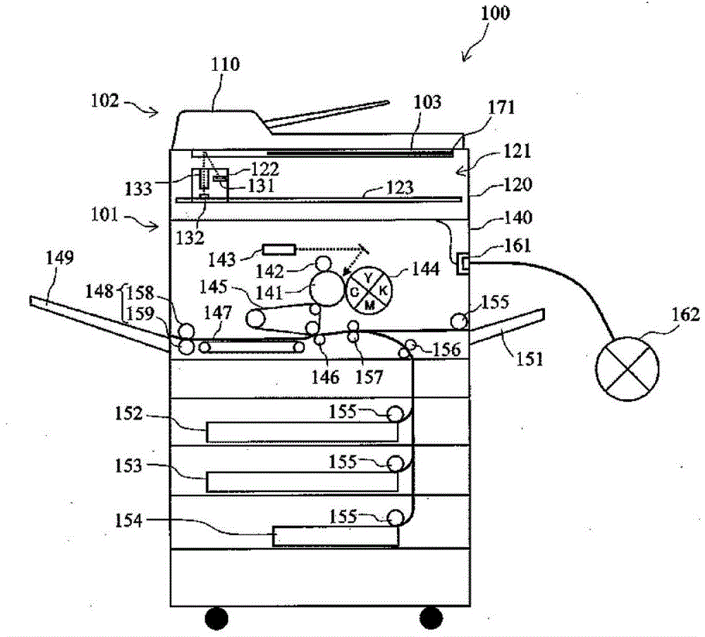
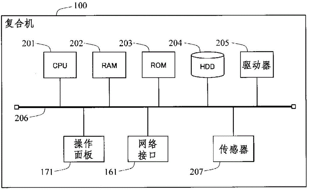
[0023] Hereinafter, embodiments of the present invention will be specifically described with reference to the drawings. Hereinafter, the present invention will be embodied as a digital multi-function peripheral having an image reading unit.

[0024] In addition, the inventors of the present invention completed the present invention by intensively studying a method of suppressing radiation noise caused by a flexible flat cable of an image reading unit for an image forming apparatus including an image reading unit and an image forming unit. The inventors of the present invention have found that the state of radiation noise varies depending on the connection structure between the metal plate disposed near the flexible flat cable and the ground member disposed in the image forming section.

[0025] figure 1 It is a configuration schematic diagram showing an example of the overall configuration of the multifunction peripheral according to the present embodiment. like figure 1 As...


PUM


Abstract

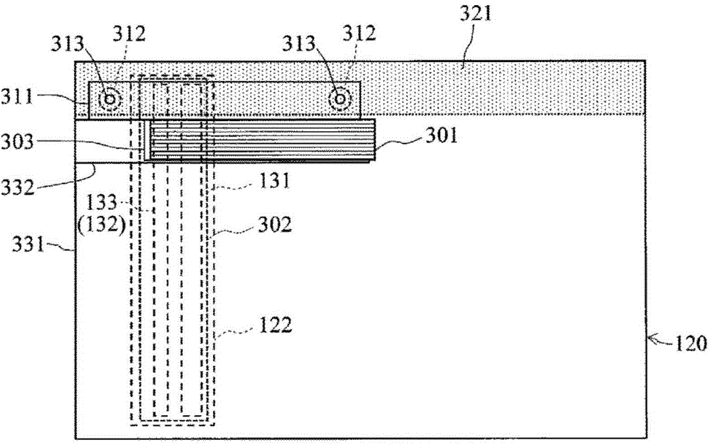
A flat cable (301) is arranged in the direction of the reciprocating movement of a carriage (122), and inputs a synchronization signal to a substrate mounted on the carriage (122). When the flat cable (301) undergoes bending deformation in response to the reciprocating movement of the carriage (122) and portions of the flat cable (301) oppose one other as a result of the bending deformation, a conductive plate (311) is supported by a case (331) while interposed between the opposing portions of the flat cable (301). Elastic members (312) electrically connect the conductive plate (311) and a grounding member (321), and have a substantial inductance component which absorbs vibration generated in an image formation unit (140) or an image reading unit (120).

Description

technical field [0001] The present invention relates to an image forming apparatus including an image reading unit that reads a document image, and an image forming unit that prints the document image read by the image reading unit on a transfer target body. Background technique [0002] Conventionally, as image reading mechanisms such as copiers, facsimile machines, scanners, and multifunction machines, structures in which a movable holder is provided under a document table (contact glass) are known. In such an image reading mechanism, by moving the carriage, it is possible to read an image of a document placed on the document table with the surface to be read facing the document table. [0003] A document reading light source for illuminating the document is mounted on the holder. In an image reading mechanism using a contact optical system, an image sensor (for example, a CMOS (Complementary Metal Oxide Semiconductor: Complementary Metal Oxide Semiconductor) image sensor...

Claims


Application Information

Patent Timeline
Patent Type & Authority Applications(China)
IPC IPC(8): G03B27/50G03G15/00H04N1/00H04N1/04
CPCG03G15/60H04N1/04H04N1/00G03G15/80H04N1/00907H04N1/00994H04N1/1061H04N2201/0094
Inventor 小林安良
Owner KYOCERA DOCUMENT SOLUTIONS INC
Learn More