
Double-diffused metal oxide transistor manufacturing method and transistor device

A technology of oxide transistor and fabrication method, applied in semiconductor device, semiconductor/solid-state device manufacturing, electrical components, etc., can solve the problems of EAS failure, burnt device, device junction temperature rise, etc.

Active Publication Date: 2019-04-26
FOUNDER MICROELECTRONICS INT
View PDF5 Cites 0 Cited by
  • Summary
  • Abstract
  • Description
  • Claims
  • Application Information

AI Technical Summary

Problems solved by technology

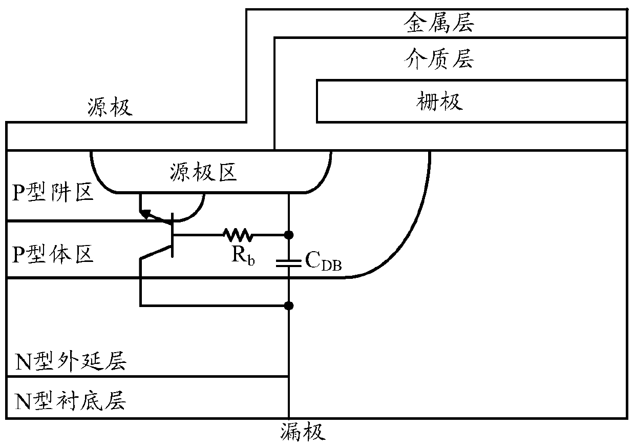
figure 2 R shown in b is the equivalent resistance of the base area. Although the emitter area of ​​the parasitic tube has been short-circuited with the base area in design, if the avalanche current is large enough, once R b The voltage drop on the drop exceeds 0.7V, at this time the V of the parasitic tube BE The junction will still be forward-conducting, so that the parasitic tube will be turned on, and the DMOS tube will lose control. Excessive continuous current will cause the junction temperature inside the device to rise rapidly, and even burn the device directly in severe cases, resulting in EAS failure.

Method used

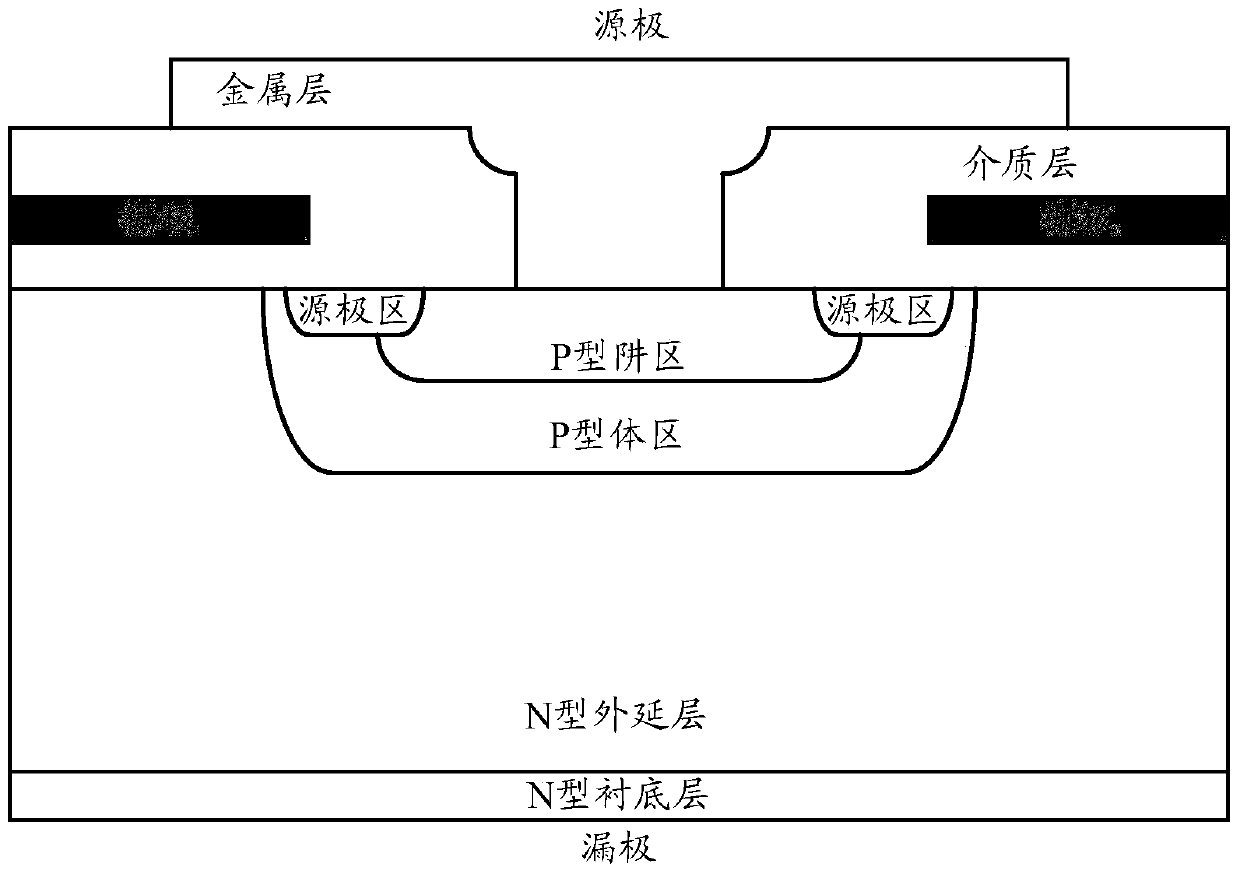

Image

  • Double-diffused metal oxide transistor manufacturing method and transistor device
  • Double-diffused metal oxide transistor manufacturing method and transistor device
  • Double-diffused metal oxide transistor manufacturing method and transistor device

Examples


Embodiment Construction

[0026] In order to be able to understand the above objectives, features and advantages of the present invention more clearly, the present invention will be further described in detail below in conjunction with the accompanying drawings and specific embodiments. It should be noted that the embodiments of the application and the features in the embodiments can be combined with each other if there is no conflict.

[0027] In the following description, many specific details are set forth in order to fully understand the present invention. However, the present invention can also be implemented in other ways different from those described here. Therefore, the present invention is not limited to the specific embodiments disclosed below. limit.

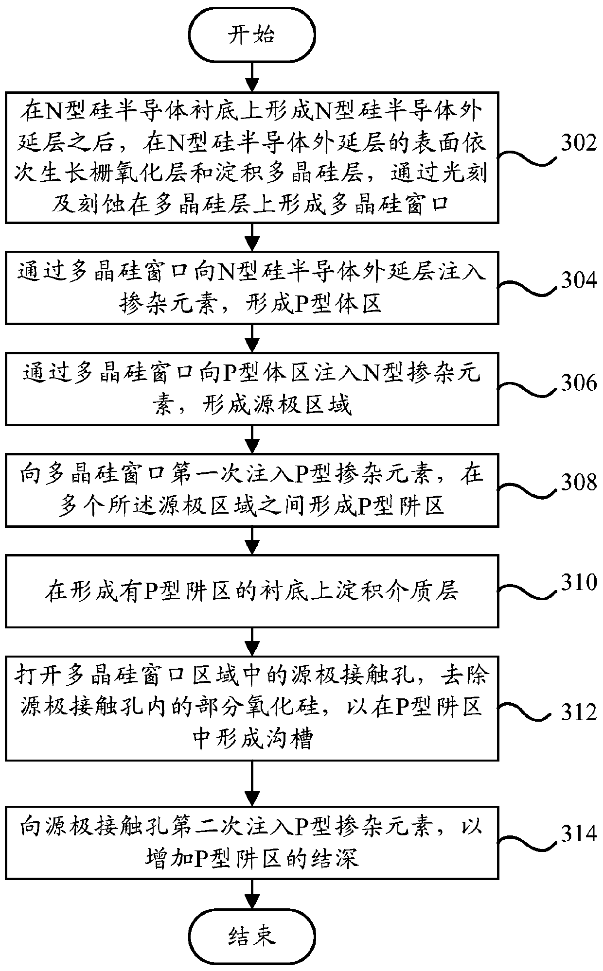
[0028] image 3 A flow chart of a method for fabricating a double diffused metal oxide transistor according to an embodiment of the present invention is shown.

[0029] Such as image 3 As shown, the method for fabricating a double diffused metal o...


PUM

PropertyMeasurementUnit
depthaaaaaaaaaa

Abstract

The invention provides a double-diffusion metal oxide transistor manufacture method and a double-diffusion metal oxide transistor device. The double-diffusion metal oxide transistor manufacture method includes the following steps that: a gate oxide layer is grown on the surface of an N type silicon semiconductor epitaxial layer, and a polycrystalline silicon layer is deposited on the surface of the N type silicon semiconductor epitaxial layer, and a polycrystalline silicon window is formed on the polycrystalline silicon layer; a doping element is injected into the N type silicon semiconductor epitaxial layer through the polycrystalline silicon window, so that P type body regions can be formed; an N type doping element is injected into the P type body regions through the polycrystalline silicon window, so that source regions can be formed; a P type doping element is injected into the polycrystalline silicon window for a first time, so that P type well regions can be formed between the plurality of source regions; a dielectric layer is deposited on the substrates of the P type well regions; source contact holes in the region of the polycrystalline silicon window are opened, and part of silicon oxide in the contact holes is removed; and the P type doping element is injected into the contact holes for a second time, so that the junction depth of the P type well regions can be increased. With the double-diffusion metal oxide transistor manufacture method and the double-diffusion metal oxide transistor device adopted, the cellular structure of the transistor can be optimized, and the base resistance of the transistor can be decreased, and the transistor can have better anti-avalanche impact ability.

Description

Technical field [0001] The invention relates to the field of semiconductor devices and their process manufacturing, in particular to a method for manufacturing a double diffused metal oxide transistor and a double diffused metal oxide transistor device. Background technique [0002] With the extensive use of power adapters, inverters, HID lighting, LED drivers and other circuits, semiconductor transistors are also used more and more, in DMOS (Double-diffused Metal Oxide Semiconductor) In the manufacturing field, with the increasingly fierce market competition, it is becoming more and more important to continuously improve the reliability of the device, and the EAS (Energy Avalanche Stress, single pulse avalanche breakdown energy) capability is an important indicator to measure the robustness of DMOS devices. , It is a parameter that characterizes the avalanche resistance of the device. The stronger the EAS ability, the better the reliability. [0003] In the prior art, the P+ (hea...

Claims


Application Information

Patent Timeline
Patent Type & Authority Patents(China)
IPC IPC(8): H01L21/336H01L21/265H01L29/78H01L29/36
CPCH01L21/266H01L29/66666H01L29/7801
Inventor 何昌蔡远飞姜春亮
Owner FOUNDER MICROELECTRONICS INT
Learn More