
Freezing and refrigerating device and defrosting control method thereof

A refrigeration device and defrosting heater technology, applied in household refrigeration devices, cooling fluid circulation devices, defrosting, etc., can solve the problems of increasing refrigerator energy consumption, temperature rise, affecting food preservation and freezing time, etc., to improve defrosting Frost effect, improved fluidity, and shortened defrosting time

Active Publication Date: 2015-07-29
HAIER SMART HOME CO LTD
View PDF6 Cites 24 Cited by
  • Summary
  • Abstract
  • Description
  • Claims
  • Application Information

AI Technical Summary

Problems solved by technology

However, the hot air generated during the defrosting process cannot be exhausted to the outside of the refrigerator. On the one hand, the hot air will enter the storage compartment of the refrigerator through the air inlet, causing the temperature in the storage compartment to rise, affecting the freshness and freezing time of food
On the other hand, after defrosting, when the storage compartment is refrigerated again, it takes a long time to recover the temperature before defrosting, which increases the energy consumption of the refrigerator.

Method used


Image

  • Freezing and refrigerating device and defrosting control method thereof
  • Freezing and refrigerating device and defrosting control method thereof
  • Freezing and refrigerating device and defrosting control method thereof

Examples


Embodiment Construction

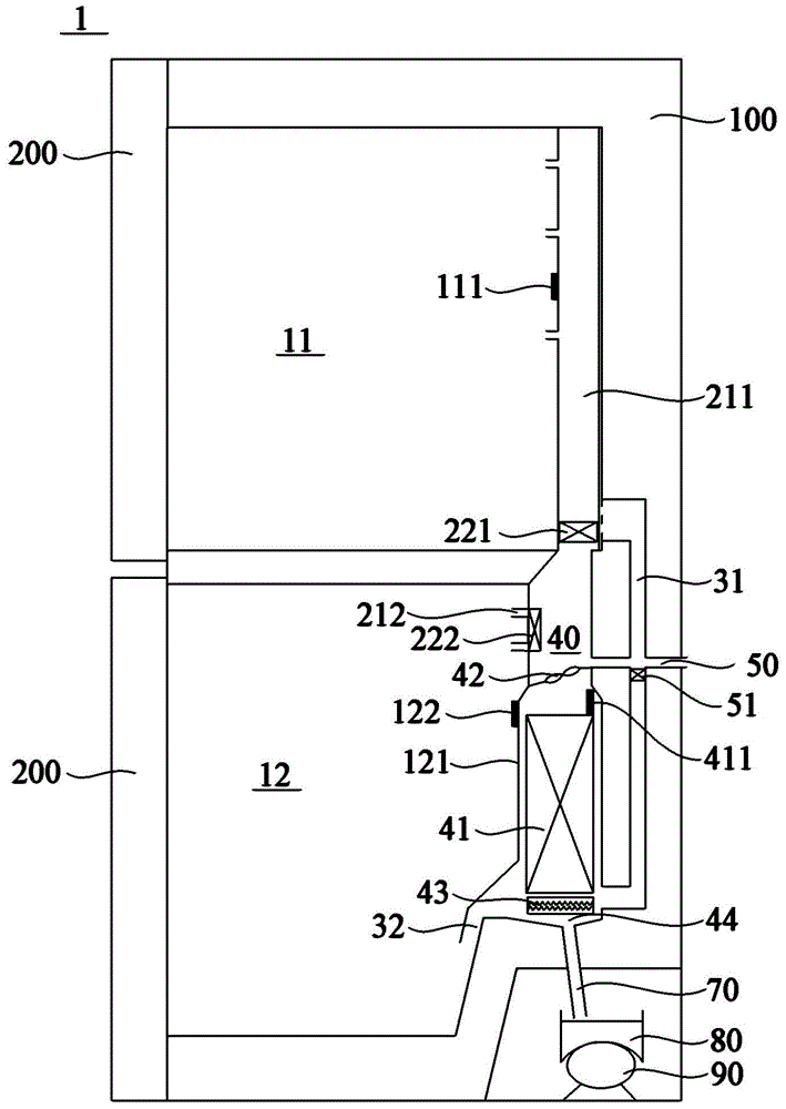
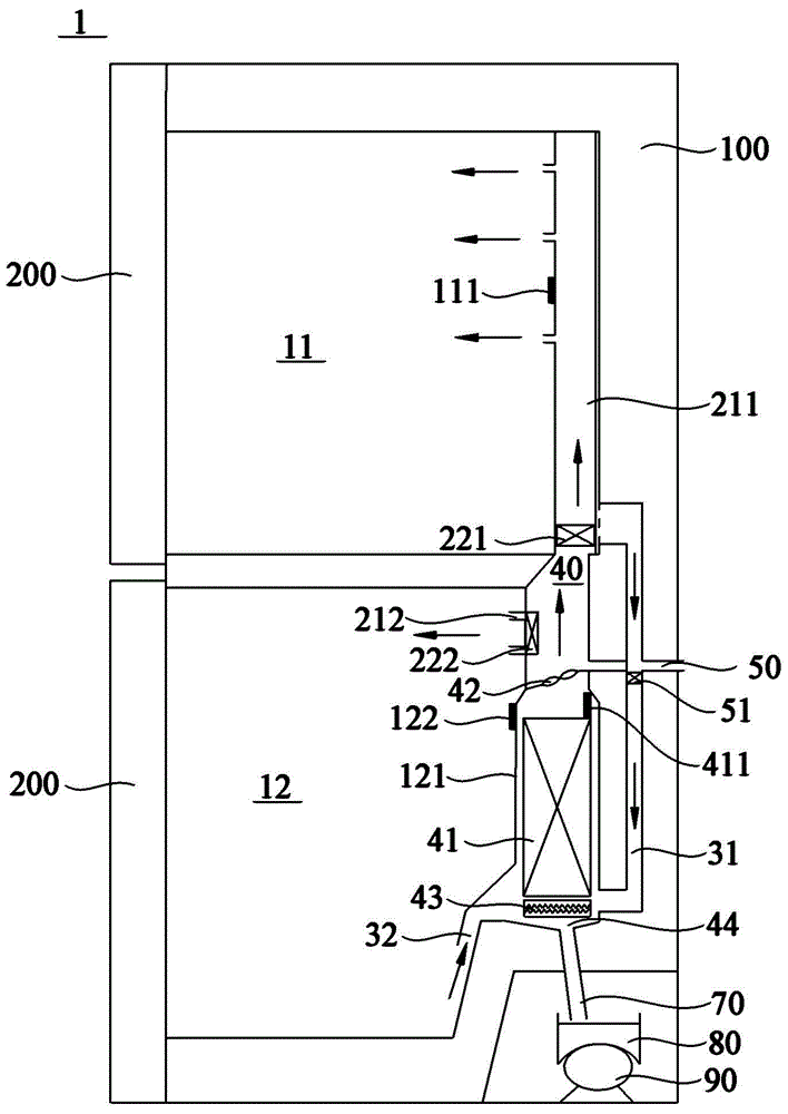
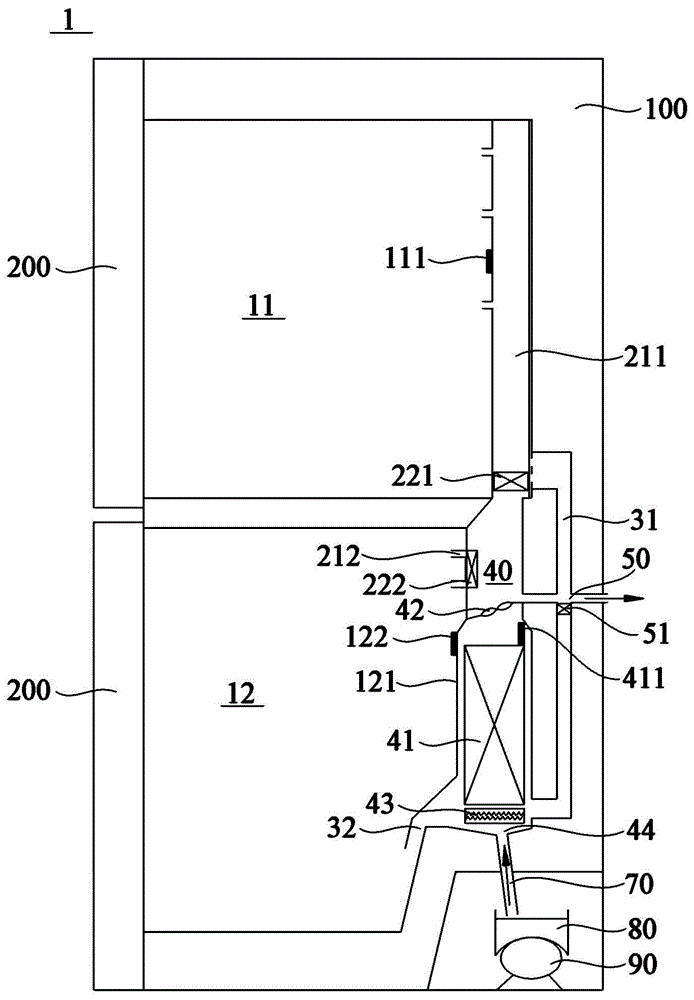
[0047] figure 1 is a schematic structural diagram of a freezer and refrigerator according to an embodiment of the present invention. Such as figure 1 As shown, the refrigerating device 1 includes a box body 100 and a door body 200 pivotally connected to the box body 100 . The inside of the box body 100 defines at least one storage compartment for storing items, a supply air path, a return air path and a cooling chamber 40 . The air supply path is configured to supply cooling airflow to at least one storage compartment. The return air path is configured to flow air from the at least one storage compartment. The cooling chamber 40 communicates with the supply air path and the return air path, and an evaporator 41 for cooling the air flowing in from the return air path, and an evaporator 41 for driving the air in the cooling chamber 40 to flow toward the supply air path are provided inside. A fan 42 and a defrosting heater 43 arranged on the evaporator. In particular, a disc...


PUM


Abstract

The invention relates to a freezing and refrigerating device and a defrosting control method of the freezing and refrigerating device. The freezing and refrigerating device comprises a box body and a door body, wherein at least one storage chamber, a supply air way, a return air way, a cooling chamber and a discharging air way are limited in the box body; the supply air way is used for supplying cooling airflow to the storage chamber; the return air way enables the airflow from the storage chamber to flow through; the cooling chamber is communicated with the supply air way and the return air way and is contained with an evaporator, a draught fan and a defrosting heater; the discharging air way is communicated with the cooling chamber and an environment space; the supply air way and the discharging air way are respectively provided with a supply air door and a discharging air door which are used for selectively switching on and / or blocking the supply air way and the discharging air way. The invention also discloses the defrosting control method of the freezing and refrigerating device. The defrosting control method comprises the steps of receiving a defrosting signal, starting the defrosting heater which is positioned on the evaporator, closing the supply air door, opening the discharging air door, enabling hot air generated by defrosting to be discharged into the environment space, and the like.

Description

technical field [0001] The invention relates to the defrosting technology of an evaporator, in particular to a freezing and refrigerating device and a defrosting control method thereof. Background technique [0002] Normally, after a period of operation of a refrigerator and other freezing and refrigerating devices, a layer of frost will form on the surface of the evaporator. The frost layer will affect the heat exchange between the evaporator and the air in the refrigerator, reducing the cooling efficiency of the evaporator, so the refrigerator must be defrosted after running for a period of time. [0003] In the prior art, heating is usually used to defrost the evaporator. However, the hot air generated during the defrosting process cannot be exhausted to the outside of the refrigerator. On the one hand, the hot air will enter the storage compartment of the refrigerator through the air inlet, causing the temperature in the storage compartment to rise, affecting the freshn...

Claims


Application Information

Patent Timeline
IPC IPC(8): F25D21/02F25D21/06
CPCF25D21/004F25D21/02F25D21/06F25D2321/00F25D21/006F25D21/08F25D21/12F25D11/00F25D17/065F25D21/14F25D2700/10
Inventor 马坚陶海波刘建如戚斐斐姬立胜
Owner HAIER SMART HOME CO LTD
Learn More