Wind-energy steady-flow energy supply method and system
A technology of wind energy and steady flow, which is applied in the field of wind energy steady flow energy supply method and system, and can solve problems affecting the wide application of wind power
- Summary
- Abstract
- Description
- Claims
- Application Information
AI Technical Summary
Problems solved by technology
Method used
Image
Examples
Embodiment 1
[0108] A wind energy steady flow energy supply method, comprising:
[0109] The first step is to convert wind energy into mechanical power;
[0110] The second step is to use the mechanical power to compress and liquefy the air to obtain liquefied air;
[0111] In the third step, the liquefied air is stored in the liquefied air storage tank 3;
[0112] The fourth step is to provide liquefied air from the liquefied air storage tank 3 to the heated fluid channel of the regenerator 4 to obtain pressurized compressed air;
[0113] In the fifth step, the pressurized compressed air is introduced into the combustion chamber 5, so that the pressurized compressed air reacts with the fuel in the combustion chamber 5 to obtain a working fluid;
[0114] In the sixth step, the working medium is introduced into a turbine 6 with more than two stages, and the turbine 6 drives the generator 7 to output electric power;
[0115] In the seventh step, the working fluid discharged from the turbi...
Embodiment 2
[0117] A wind energy steady flow energy supply system, such as figure 1 As shown, it includes: fan 1, air liquefaction unit 2, liquefied air storage tank 3, regenerator 4, combustion chamber 5, turbine 6 and generator 7, the fan 1 outputs power to the air liquefaction unit 2, The liquefied air outlet of the air liquefaction unit 2 communicates with the inlet of the liquefied air storage tank 3, the outlet of the liquefied air storage tank 3 communicates with the inlet of the heated fluid channel of the regenerator 4, and the regenerator The outlet of the heated fluid channel of the heater 4 communicates with the combustion chamber 5 , the working medium outlet of the combustion chamber 5 communicates with the working medium inlet of the turbine 6 , and the turbine 6 is connected to the generator 7 To output power, the working fluid outlet of the turbine 6 communicates with the inlet of the heating fluid channel of the regenerator 4 .
Embodiment 3
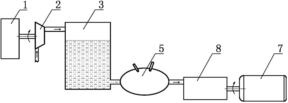
[0119] A wind energy steady flow energy supply method, comprising:
[0120] The first step is to convert wind energy into mechanical power;
[0121] The second step is to use the mechanical power to compress and liquefy the air to obtain liquefied air;
[0122] In the third step, the liquefied air is stored in the liquefied air storage tank 3;
[0123] In the fourth step, the liquefied air is introduced into the combustion chamber 5 from the liquefied air storage tank 3, so that the liquefied air reacts chemically with the fuel in the combustion chamber 5 to obtain a working medium;
[0124] In the fifth step, the working fluid is introduced into the multi-stage boundary-changing fluid mechanism 8, and the multi-stage boundary-changing fluid mechanism 8 drives the generator 7 to output electric power.
PUM
 Abstract
Description
Claims
Application Information
 - R&D Engineer
- R&D Manager
- IP Professional
- Industry Leading Data Capabilities
- Powerful AI technology
- Patent DNA Extraction
Browse by: Latest US Patents, China's latest patents, Technical Efficacy Thesaurus, Application Domain, Technology Topic, Popular Technical Reports.
© 2024 PatSnap. All rights reserved.Legal|Privacy policy|Modern Slavery Act Transparency Statement|Sitemap|About US| Contact US: help@patsnap.com


