
Novel positioning mechanism for air feeding rocker arm shaft

An intake rocker arm and shaft positioning technology, which is applied to mechanical equipment, engine components, machines/engines, etc., can solve problems such as unevenness, leaking, leakage, and O-ring rubber seals, and achieve easier layout.

Inactive Publication Date: 2015-07-29
CHINA NORTH ENGINE INST TIANJIN
View PDF6 Cites 0 Cited by
  • Summary
  • Abstract
  • Description
  • Claims
  • Application Information

AI Technical Summary

Problems solved by technology

[0003] The use of this positioning structure only initially meets the functional requirements of the rocker shaft positioning. Since the cylinder diameter and cylinder center distance are small and the structure is compact, there are the following deficiencies: First, the camshaft support body is in contact with the cylinder head. The sealing structure between the surfaces, that is, the O-shaped rubber sealing ring is difficult to arrange; the second is that because the single-piece cylinder head is used, the positioning mechanism of the intake rocker arm is arranged between the two cylinders, which will cause the oil to be not tightly sealed and cause leakage. The problem of dripping; the third is that due to the limitation of compact structure, only one positioning bolt or pin can be arranged in this positioning structure. After installation, it is easy to cause the intake rocker shaft to tilt in the hole and not be horizontal

Method used


Image

  • Novel positioning mechanism for air feeding rocker arm shaft

Examples


Embodiment Construction

[0015] Specific embodiments of the present invention will be described in detail below in conjunction with the accompanying drawings.

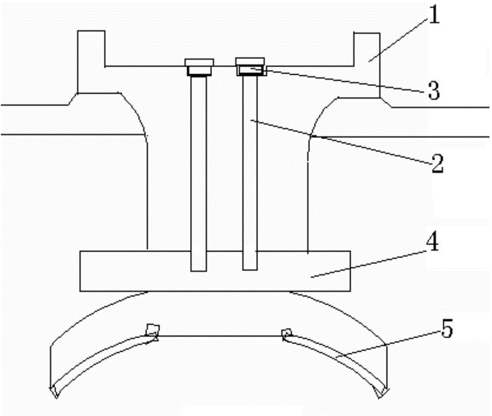
[0016] A new type of air intake rocker shaft positioning mechanism, such as figure 1 As shown, it includes the camshaft support body 1 and the intake rocker shaft 4 installed in the installation hole of the intake rocker shaft on it; the intake rocker shaft 4 is positioned on the integral cam by two positioning bolts 2 In the installation hole on the support column between the two cylinders on the shaft support body 1, the top surface of the camshaft support body 1, that is, the side away from the cylinder head is provided with two positioning holes, and the positioning bolts 2 pass through the camshaft The positioning hole on the top surface of the support body 1 is connected to the intake rocker shaft 4 through threaded engagement; the positioning hole is arranged above the camshaft support body 1, which better solves the problem of poor oil...


PUM


Abstract

The invention provides a novel positioning mechanism for an air feeding rocker arm shaft. The mechanism comprises a cam shaft supporting body, and an air feeding rocker arm shaft which is mounted in an air feeding rocker shaft mounting hole, wherein the air feeding rocker arm shaft is positioned into a mounting hole in a supporting vertical column between two cylinders on an integral cam shaft supporting body through two positioning bolts; two positioning holes are formed in one surface of the top surface of the cam shaft supporting body, far away from cylinder covers; the positioning bolts pass through the positioning holes in the top surface of the cam shaft supporting body to engage and be connected with an air feeding rocker arm shaft. The mechanism has the advantages and benefits that a sealing structure between the matching contact surfaces of the cam shaft supporting body and the cylinder covers is easily arranged; the problem of space for an air feeding rocker arm shaft positioning mechanism is out of consideration; the positioning mechanism is arranged at the upper part, instead of the lower part, so that the problem of poor engine oil sealing can be solved well; the two positioning bolts or pins solve the problem that single bolt is difficult to achieve positioning reliability, namely, the horizontality of the air feeding rocker arm shaft.

Description

technical field [0001] The invention belongs to the technical field of engine components, and in particular relates to a novel intake rocker arm shaft positioning mechanism. Background technique [0002] In the prior art, the engine with a relatively compact structure has a small cylinder diameter and cylinder center distance. If an integral camshaft support body and a single cylinder head structure are used, the intake rocker arm shaft must be fixedly installed on the camshaft. In the intake rocker shaft mounting hole of the shaft support body, when solving the positioning problem of the intake rocker arm shaft, the positioning structure is mostly designed on the bottom surface of the camshaft support body, that is, the side that is in contact with the cylinder head. [0003] The use of this positioning structure only initially meets the functional requirements of the rocker shaft positioning. Since the cylinder diameter and cylinder center distance are small and the struct...

Claims


Application Information

Patent Timeline
IPC IPC(8): F01L1/18F01L1/047
Inventor 王艳丽王根全胡立萍强智臻张丽
Owner CHINA NORTH ENGINE INST TIANJIN
Learn More