
Adjustable type efficient residue-liquid separation device

A slag-liquid separation and adjustable technology, applied in filtration separation, separation methods, fixed filter element filters, etc., can solve the problems of insufficient practicability, low work efficiency, inconvenient operation, etc., and achieve simple structure and convenient operation. , a wide range of effects

Inactive Publication Date: 2015-07-29
重庆市渝中区市政管理局环卫三所
View PDF5 Cites 5 Cited by
  • Summary
  • Abstract
  • Description
  • Claims
  • Application Information

AI Technical Summary

Problems solved by technology

However, most of the existing related separation equipment uses the method of filtration to separate the slag and liquid. This kind of equipment generally has the problems of inconvenient operation and low work efficiency.
More importantly, in the prior art, generally according to different slag quality and concentration of slag liquid, different slag-liquid separation equipment needs to be selected, the scope of application is narrow, and the practicability is not strong enough.

Method used


Image

  • Adjustable type efficient residue-liquid separation device

Examples


no. 1 example

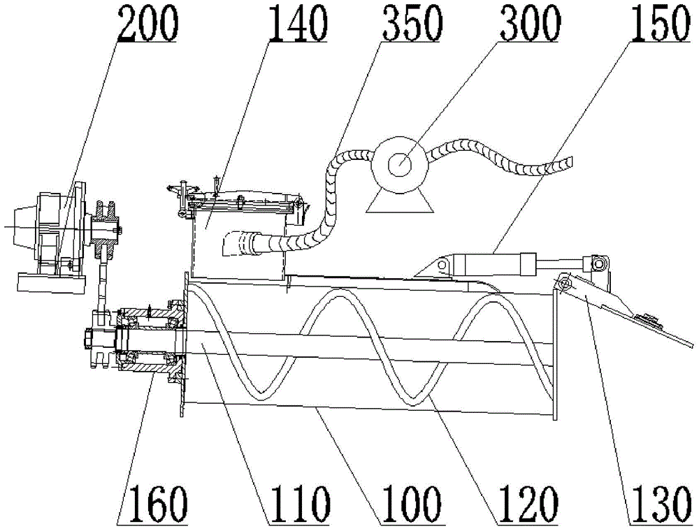
[0044] The first embodiment, refer to figure 1 , The adjustable high-efficiency slag-liquid separation device includes a separation drum 100 and a rotating shaft 110 extending into the separation drum 100. The separation drum 100 is provided with a slag liquid inlet, a filter hole, a slag discharge port, and a slag discharge port for blocking the slag discharge port. The slag liquid inlet is connected with a sewage suction device, the part of the rotating shaft 110 located in the separation cylinder 100 is provided with a screw press blade 120, and the part located outside the separation cylinder 100 is connected with a motor 200, The output end of the screw press blade 120 corresponds to the slag discharge port.

[0045]Wherein, the slag liquid inlet is arranged at one end of the separation cylinder 100, and the slag discharge port is arranged at the other end; The length direction and the circumferential direction are arranged at intervals; the flip cover 130 is hinged on t...

no. 2 example

[0069] In the second embodiment, the implementation principle and the technical effect of the device provided by the embodiment of the present invention are the same as those in the first embodiment. corresponding content.

[0070] In this embodiment, the separation cylinder 100 is in the shape of a truncated cone, including a large end close to the slag liquid inlet and a small end close to the slag discharge port, and the pitch of the screw press blade 120 gradually decreases from the large end to the small end .

[0071] The purpose of arranging the separation cylinder 100 and the screw press blades 120 in this way is that the solid slag is gradually squeezed by the inner wall of the separation cylinder 100 during the process of being pushed by the screw press blades 120 to the slag discharge port, so as to optimize the pressing effect of the screw press blades 120 .


PUM


Abstract

The invention provides an adjustable type efficient residue-liquid separation device, and belongs to the technical field of sewage and pollutant treatment. The device comprises a separation cylinder and a rotating shaft extending into the separation cylinder, wherein a residue-liquid inlet, filter holes, a residue discharge port and a lifting cover used for covering the residue discharge port are arranged on the separation cylinder; the residue-liquid inlet is communicated with a pollution absorption device; a spiral squeezing blade and a motor are arranged on the rotating shaft; an output end of the spiral squeezing blade corresponds to the residue discharge port. The adjustable type efficient residue-liquid separation device adopts a targeted creative design according to function elements required by a strong pollution absorption and residue-liquid separation vehicle, and efficient, rapid and complete residue-liquid separation effect is achieved by adopting different separation methods according to different residue-liquid mixing kinds and states; after the device is assembled in the strong pollution absorption vehicle, various function elements of the strong pollution absorption vehicle can be displayed sufficiently.

Description

technical field [0001] The invention relates to the technical field of sewage treatment, in particular to an adjustable high-efficiency slag-liquid separation device. Background technique [0002] In the sewage treatment, papermaking and other industries, the separation of slag such as paper scraps from the liquid is a key step in sewage treatment. In the prior art, the slag-liquid separation is generally performed manually, which inevitably leads to low work efficiency. [0003] At present, there are also some slag-liquid separation equipment on the market. However, most of the existing related separation equipment uses the method of filtration to separate the slag and liquid, and such equipment generally has the problems of inconvenient operation and low work efficiency. More importantly, in the prior art, generally, different slag-liquid separation equipment needs to be selected according to different slag quality and slag-liquid concentration, the scope of application ...

Claims


Application Information

Patent Timeline
Patent Type & Authority Applications(China)
IPC IPC(8): B01D29/11B01D29/82C02F11/12
Inventor 杨朝虹钱刚
Owner 重庆市渝中区市政管理局环卫三所
Learn More