
Brake ring

A technology of brake rings and brake parts, which is applied in the field of brake rings, can solve the problems of low braking effect, insufficiently filled products, and air trapped, so as to achieve effective performance, improve processing reliability, and reduce reprocessing Effect

Active Publication Date: 2015-07-29
ALBERT HANDTMANN MASCHFABRICK
View PDF11 Cites 1 Cited by
  • Summary
  • Abstract
  • Description
  • Claims
  • Application Information

AI Technical Summary

Problems solved by technology

[0009] - If the braking effect is too low, trapped air and underfilled product will result

Method used


Image

  • Brake ring
  • Brake ring
  • Brake ring

Examples


Embodiment Construction

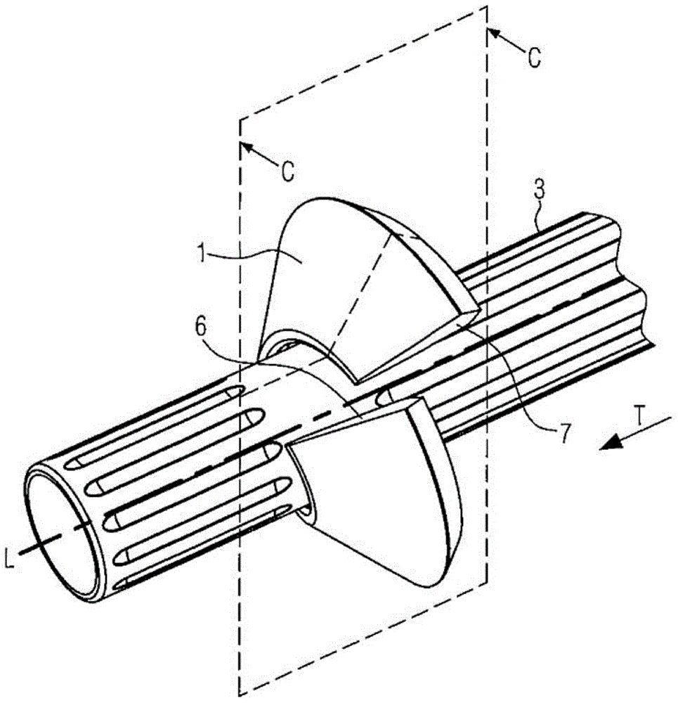
[0084] figure 1 A first embodiment of the brake ring 1 according to the invention is shown in perspective. The reference numeral 3 designates a filling tube via which the pasty substance is conveyed into the casing 11 in a known manner, wherein the casing, not shown here, is pulled over the filling tube 3 during operation. The pasty substance is passed through in a generally known manner Figure 14 The hopper 13 and feeding mechanism 17 shown in Fig. 2 fill the filling tube 3 intermittently or continuously, which will not be shown in more detail here.

[0085] In mechanical sausage production, the casing 11 is first placed on the stuffing tube 3 or covers the free end 3a of the stuffing tube 3 . Next, the casing brake 10 (see image 3 ) is located on the filling pipe 3. The casing brake 10 can be positioned at different positions in the conveying direction T of the casing (here, for the sake of simplicity, the casing is not shown, see Figure 13 ).

[0086] According to ...


PUM


Abstract

Various systems and methods are provided for the manufacture of sausages. In one example, a method for manufacturing sausages with a filling machine comprises ejecting a mass through a filling tube into a sausage casing ruffled on the filling tube, and exerting a brake force on the sausage casing via a sausage casing brake on a braking area of a brake ring pressing onto the sausage casing, wherein the braking area extends around a longitudinal axis of the filling tube such that the braking area presses onto a part, and not the entirety, of a circumference of the sausage casing in a plane perpendicular to the longitudinal axis, and wherein the brake force is distributed in a direction along the longitudinal axis.

Description

technical field [0001] The present invention relates to a method for producing sausages with a filling machine according to the preamble of variant 1 and to brake rings, casing brakes and filling tubes according to the preamble of variants 3, 10 and 17. Background technique [0002] In mechanical sausage production, the casings are first placed on the filling tube at the outlet of the unit. Next, the casing stopper is positioned at the end of the filling tube. Casing brakes are used to keep the casing stretched at the point of filling (ie at the end of the filling tube) when the casing is being filled with substance (ie sausage meat). This is a prerequisite for eg the production of high quality, tightly packed sausages. [0003] In addition, when the casing is twisted off, the casing brake causes the not yet filled casing to turn along the filling tube. Twisting is the method used to separate lengths of sausage. When processing natural packaging, the separation of the ca...

Claims


Application Information

Patent Timeline
Patent Type & Authority Applications(China)
IPC IPC(8): A22C11/02
CPCA22C11/0263
Inventor M·贝齐特勒J·弗拉赫M·哈姆乐W·普芬德尔G·施力塞尔S·鲁特尔J·雷克斯
Owner ALBERT HANDTMANN MASCHFABRICK
Learn More